


Following the stages of an axial turbine
An open casing reveals repeated blade rows around a common shaft. This assembly places the rotor stages, stationary guide vanes and bearing supports in view without hiding them behind a complete housing.
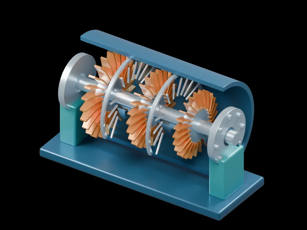
Inside the assembly
Three copper-coloured rotor stages sit along the shaft, interleaved with pale stationary guide-vane rows. The blue partial casing and base support the assembly. Inspect the gap between adjacent rows and the shaft supports at the ends. Blade shape and spacing serve as visual illustrations rather than an aerodynamic specification.
Scientific explanation
A turbine extracts shaft work by changing the angular momentum of the fluid through a moving blade row. Euler’s relation expresses specific work using blade speed and the tangential component of absolute fluid velocity at inlet and exit. In a representative axial row at similar radii, changes in fluid swirl are central to the energy exchange.
- wₜ
- Specific work extracted by the rotor (J/kg)
- U₁, U₂
- Blade speeds at rotor inlet and exit (m/s)
- Vθ₁, Vθ₂
- Absolute tangential fluid velocities at inlet and exit (m/s)
Steady mean-flow energy transfer with a consistent sign convention. The visual model supplies no velocity triangles, pressure ratio or efficiency.
Explore the model
- Count the three rotor stages and distinguish their blades from the stationary rows.
- Follow the shaft to the bearing supports at both ends.
- View the assembly along its axis to compare the annular passages.
From geometry to engineering
A performance study would define working fluid, mass flow, inlet state and rotational speed, then resolve flow turning and losses. Rotor strength, blade vibration and thermal clearances require additional analyses.