


Six electrons: reading carbon's orbital occupation
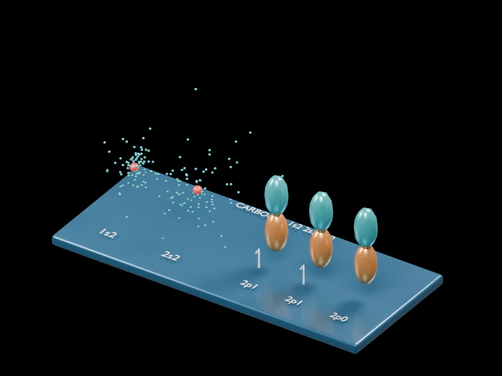
Separated teaching shapes make the occupation of carbon's s and p subshells readable. The layout is an orbital diagram expressed in three dimensions, not the spatial shape of a single carbon atom.
Inside the assembly
Two spherical sample groups labelled 1s2 and 2s2 stand beside three paired-lobe shapes. The first two p shapes carry single occupation indicators and the third is empty. Positions are separated for comparison. The s clouds and p surfaces are schematic; in an atom these orbitals share a nuclear centre.
Scientific explanation
Neutral carbon has six electrons. Its ground-state configuration fills 1s and 2s, then places two electrons in separate 2p orbitals with parallel spin projections before pairing. The choice of displayed p axes is a convention for a degenerate set.
- 1s, 2s, 2p
- Subshell labels
- Superscript
- Number of electrons in the subshell
- Single indicators
- Occupation of two different p orbitals
Isolated neutral atom in its ground state. This is not an sp² or sp³ hybridisation model; the schematic 2s shape does not resolve its radial node.
Explore the model
- Read the occupation labels from 1s to 2p.
- Compare the two occupied p shapes with the empty one.
- Distinguish the separate teaching positions from real overlapping orbitals.
From geometry to engineering
Compare carbon with neighbouring elements, then treat molecular bonding and hybridisation as separate models requiring additional context.