


From impeller to outlet: reading a centrifugal pump
The open pump casing reveals the relationship between a curved impeller and the surrounding discharge passage. Use the model to examine the assembly from the motor below to the outlet beside the impeller.
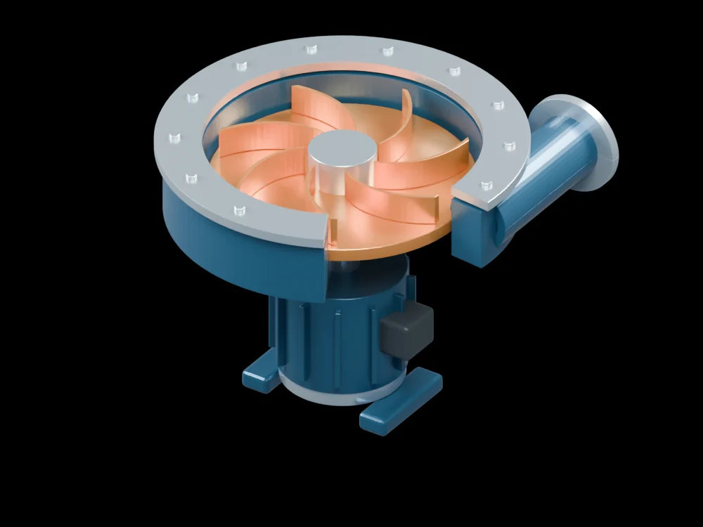
Inside the assembly
Copper-coloured vanes sit on the impeller disc inside a blue cutaway casing. The flange, fasteners and tangential outlet make the casing easy to distinguish from the rotor. Below it, the motor body has cooling fins and mounting feet. The cover opening exposes the assembly for inspection.
Scientific explanation
A rotating impeller transfers energy to liquid. A useful hydraulic output is the product of fluid density, gravity, flow rate and head. Shaft input must be larger when efficiency is below one. The operating flow and head require a pump characteristic and system information; they cannot be read from a rendered shape.
- Pₕ, Pshaft
- Hydraulic output and shaft input power (W)
- ρ, g
- Liquid density (kg/m³) and gravitational acceleration (m/s²)
- Q, H
- Volume flow (m³/s) and pump head (m)
- η
- Pump efficiency as a fraction
Steady incompressible flow for the power balance. No flow rate, speed, head or efficiency is assigned to this geometry.
Explore the model
- Begin at the central impeller eye and follow the curved vanes outward.
- Rotate towards the outlet to inspect how it meets the casing.
- Compare stationary casing features with the impeller and its drive axis.
From geometry to engineering
A design study would specify the liquid, speed and duty point, then investigate the hydraulic passages, clearances, seals and cavitation margin. The model provides an assembly view for that discussion.