


Brushes, commutator and torque in a DC motor
The cutaway exposes the current-carrying armature and the mechanism that switches its connections. Inspect the lower commutator before following the copper conductors upwards.
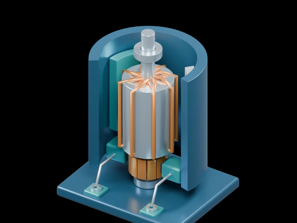
Inside the assembly
Two magnet sectors sit inside an open magnetic yoke. Armature conductors surround the central iron stack and shaft. Copper commutator segments sit below the armature, between two dark carbon brushes in teal holders. The base carries the external DC terminals.
Scientific explanation
A current loop in a magnetic field experiences a torque. Its magnitude depends on current, loop area, field strength and orientation. A brushed motor switches the armature connections through the commutator as it turns, allowing useful rotational torque to continue. The single-loop expression explains the principle rather than the output of this multi-coil geometry.
- τ
- Torque on the ideal current loop (N·m)
- N, I
- Number of turns and current (A)
- A, B
- Loop area (m²) and uniform magnetic flux density (T)
- θ
- Angle between the loop normal and magnetic field
Ideal planar loop in a uniform field. The static cutaway has no commutation simulation, electrical rating or calibrated torque constant.
Explore the model
- Find the insulating gaps between copper commutator segments.
- Locate each brush where it meets the commutator.
- Compare the stationary magnet sectors with the wound armature.
From geometry to engineering
A motor study would include the back-EMF constant, resistance, brush contact behavior, inertia and thermal limits before estimating speed or load capability.