


Weight against water: exploring a gravity dam section
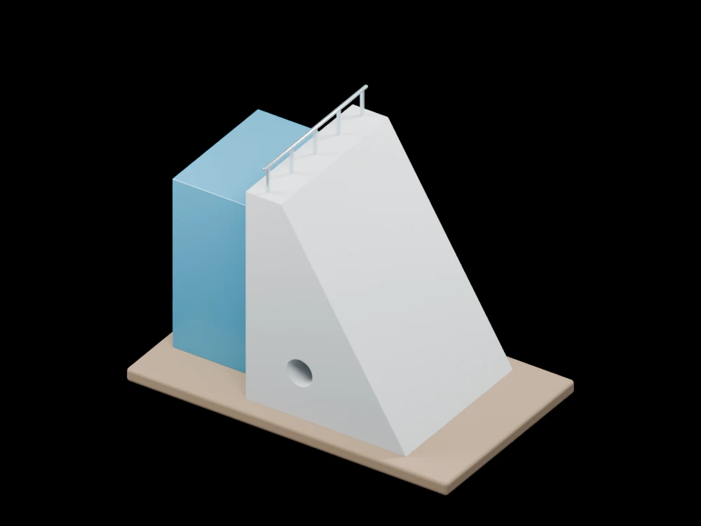
A broad dam section stands beside an illustrative reservoir. The open surroundings make its upstream face, downstream slope and inspection gallery easy to compare.
Inside the assembly
The concrete section widens towards a foundation slab. A blue reservoir volume touches the upstream face, while a gallery opening passes through the lower section. The crest carries a narrow rail and the base includes drainage indications. Reservoir extent and internal openings are simplified for display.
Scientific explanation
In still water of uniform density, gauge pressure increases with depth. Integration over a vertical face gives a horizontal resultant per unit width of one half density times gravity times water depth squared. Dam stability also depends on self-weight, uplift, foundation behaviour and other load cases.
- p, h
- Gauge pressure (Pa) and depth below the water surface (m)
- ρ, g
- Water density (kg/m³) and gravitational acceleration (m/s²)
- H, F/b
- Water depth (m) and horizontal force per unit width (N/m)
Static reservoir and a vertical upstream face. No waves, uplift distribution, seismic load or tailwater is calculated.
References
OpenStax · Fluids, density and pressure U.S. Bureau of Reclamation · Design of gravity damsExplore the model
- Compare the narrow crest with the broad base.
- Locate the gallery opening and its position within the section.
- Identify the water-contact face and the downstream slope.
From geometry to engineering
A dam assessment requires site investigations and specialised hydraulic, geotechnical and structural analysis. This section illustrates geometry and a basic pressure relation only.