


Two lobes and a node: exploring hydrogen 2p
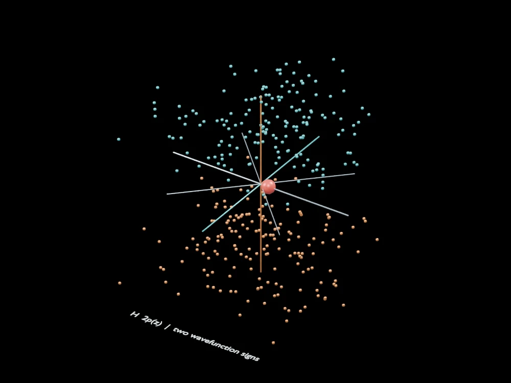
Two coloured sample regions sit on opposite sides of a reference plane. The view emphasises the angular structure of a 2p orbital and the absence of density in its nodal plane.
Inside the assembly
Teal and copper dots mark the two signs of the real 2pz wavefunction. Thin lines identify the z=0 plane and coordinate axes. Sampling uses a distribution proportional to z² exp(−r/a0), restricted to the display region and enlarged. The red nucleus marker is deliberately oversized.
Scientific explanation
A real 2pz orbital has a positive lobe and a negative lobe separated by a plane where the wavefunction is zero. Probability is the squared magnitude, so both signs give nonnegative density. The two colours indicate phase sign, not positive and negative electric charge.
- θ
- Polar angle measured from the z axis
- r, a0
- Radial distance and Bohr radius
- ψ2pz
- A real hydrogen 2p wavefunction oriented along z
Ideal hydrogen 2p state. The finite sampled region omits distant tails, and marker positions are not electron trajectories.
References
OpenStax · Development of quantum theoryExplore the model
- View the two lobes from the side.
- Locate the reference plane between them.
- Rotate around the z axis and distinguish sign colour from probability density.
From geometry to engineering
Compare 2px and 2py as different orientations, then examine nodes and signs in higher orbitals without treating their surfaces as solid objects.