


The squirrel cage and the rotating magnetic field
The open stator lets you inspect a rotor normally hidden inside the motor. Distinguish the stationary coil groups from the bars and end rings connected to the shaft.
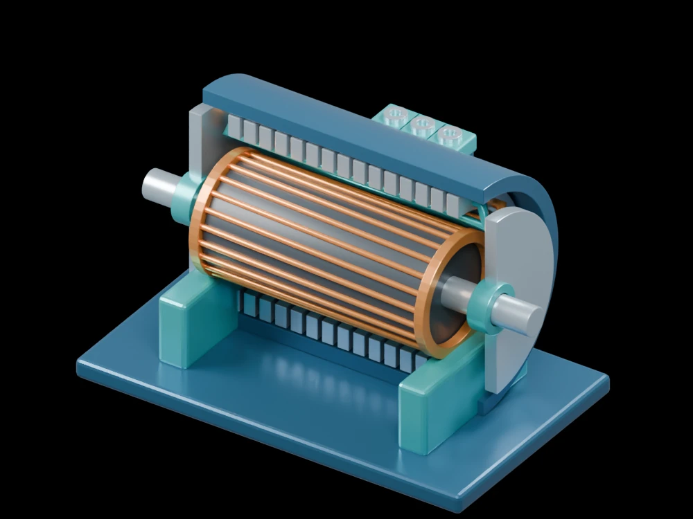
Inside the assembly
A partial blue housing supports steel-coloured stator laminations and coil groups. Conducting bars run along the dark rotor and join end rings at both ends. The shaft passes through two bearings; a terminal box identifies the three-phase supply connection.
Scientific explanation
A balanced three-phase supply creates a rotating magnetic field. Relative motion between that field and the cage induces rotor currents and produces torque. In normal motoring operation the rotor runs below synchronous speed. The fractional difference is slip; synchronous speed depends on supply frequency and pole count.
- nₛ, nᵣ
- Synchronous field and rotor speeds (rpm)
- f, P
- Electrical frequency (Hz) and total number of poles
- s
- Slip as a fraction
Steady balanced motoring operation. The display coil groups do not define a manufactured winding schedule, pole count or torque-speed characteristic.
Explore the model
- Trace one cage bar into the conducting end rings.
- Look through the housing to distinguish the stator and rotor.
- Follow the shaft through the two bearing supports.
From geometry to engineering
Motor analysis needs the winding layout, material properties, equivalent-circuit parameters and mechanical load. Rotor heating and starting behavior require additional calculations.