


Rows, columns and time: an eight-by-eight LED matrix
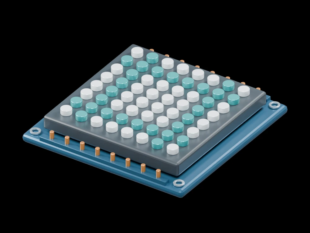
Sixty-four lenses form a compact display. Orbit underneath the board to compare the repeated emitters with the separate row and column interconnect planes.
Inside the assembly
An eight-by-eight array sits above a dark carrier on a blue board. Sixteen edge terminals represent eight row and eight column connections. The two interconnect directions occupy separate levels; apparent crossings in a flat view do not mean electrical contact. Lens colours show an illustrative fixed pattern.
Scientific explanation
A multiplexed display selects one row at a time and drives the desired columns during that interval. With equal scan slots and eight rows, an enabled pixel is driven for at most one eighth of the cycle. Average current follows duty cycle; peak current must remain within the selected LED and driver ratings.
- D
- Pixel duty fraction for one active row per slot
- Iavg, Ipeak
- Average and on-state LED current (A)
Uniform row timing with blanking neglected. Brightness is not calculated; the model has no powered driver or current-limit simulation.
Explore the model
- Count eight rows and eight columns.
- Follow the two interconnect planes under the carrier.
- Compare the number of terminals with the number of emitters.
From geometry to engineering
Choose a current-regulated driver, refresh timing and blanking interval, then test ghosting, thermal limits and perceived brightness.