


Inside a spiral-wound membrane module
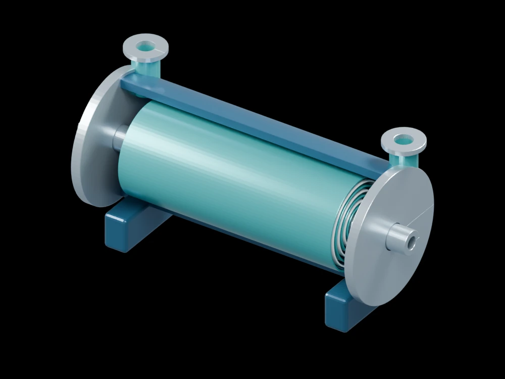
A cutaway pressure shell exposes repeated membrane layers around a collection tube. The arrangement helps distinguish feed-side passages from the permeate collection path.
Inside the assembly
Alternating pale and teal partial layers surround a central perforated tube. End flanges and two external nozzles locate the module in a pressure housing. The concentric partial leaves are a simplified illustration of a spiral-wound element; spacers, glued envelopes and the continuous winding are not fully reproduced.
Scientific explanation
In a simplified reverse-osmosis model, water flux responds to hydraulic pressure difference minus osmotic pressure difference. A permeability coefficient relates this net driving pressure to flux. Concentration polarisation, fouling and temperature can alter the effective response.
- Jw
- Water volume flux (m/s)
- A
- Water permeability coefficient (m/Pa·s)
- ΔP, Δπ
- Hydraulic and osmotic pressure differences (Pa)
Simplified solution-diffusion relation with a specified membrane coefficient. No rejection percentage or operating pressure is assigned.
Explore the model
- Look through the cutaway at the repeated membrane layers.
- Find the collection tube and its illustrative perforations.
- Compare the feed-side ports with the axial collection path.
From geometry to engineering
Choose a membrane using feed chemistry and separation targets, then assess recovery, fouling control, pressure loss and cleaning requirements.