


Counting motion with a slotted optical encoder
Repeated openings around a disc turn rotation into a pattern that light sensors can detect. Two sensing positions make direction information possible.
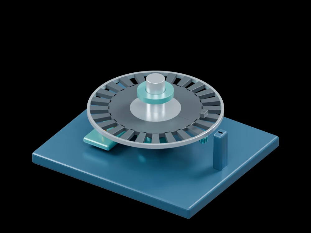
Inside the assembly
A segmented disc rotates with the central shaft between supports. Twenty-four repeating opaque sectors alternate with openings. Two optical channels are placed a quarter pitch apart around the rim, with electronics represented on the base. This is a static geometry study; the rendered disc does not emit measured pulses.
Scientific explanation
Two channels in quadrature change state in different sequences for opposite directions. Counting every rising and falling edge gives four counts per pattern period. For N periods per revolution, the ideal angular count increment is 360 degrees divided by 4N. Resolution does not establish measurement accuracy.
- N
- Optical pattern periods per revolution
- Δθ
- Angular increment per quadrature edge (degrees)
Ideal digital quadrature and four-edge decoding. Real alignment, interpolation, contamination and missed edges affect performance.
Explore the model
- Locate both sensing channels near the rim.
- Follow an opening through the disc thickness.
- Compare the pattern pitch with the offset between sensors.
From geometry to engineering
Specify an optical emitter, detector, threshold circuit and counter. Verify channel phase and maximum count rate using actual waveforms.