


A stationary catalyst bed: reading a packed reactor
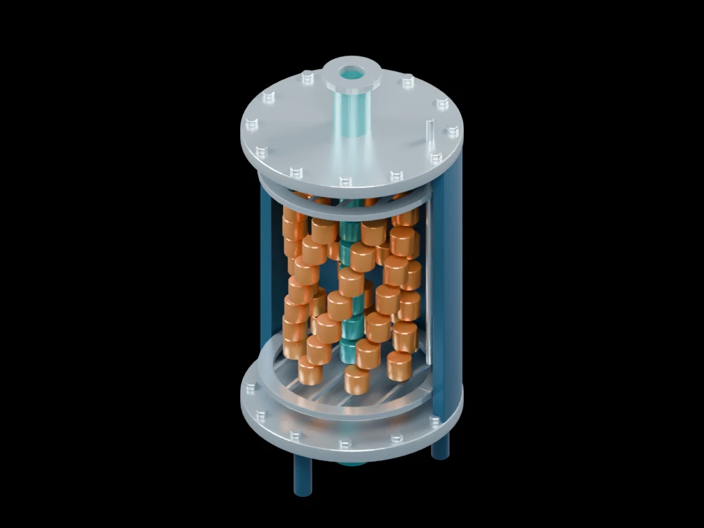
The open shell exposes catalyst pellets between two support grids. The model helps separate the stationary solid bed from the fluid passages through it.
Inside the assembly
Seven layers of enlarged pellets occupy the middle of the vessel. Grids above and below illustrate distribution and support, while a slender thermowell runs beside the bed. Flanged heads and process ports complete the assembly. Regular pellet placement improves visibility; a real randomly packed bed would have a different void structure.
Scientific explanation
A steady species balance over a small catalyst mass relates the change in molar flow to reaction rate per unit catalyst mass. For a consumed reactant the rate is negative, so its molar flow decreases down the bed. Pressure drop and heat transfer can change the local reaction rate.
- FA
- Molar flow of species A (mol/s)
- W
- Cumulative catalyst mass (kg)
- r′A
- Net formation rate per catalyst mass (mol/kg·s)
Ideal steady axial flow with no axial mixing in this balance. Pellets are illustrative; no catalyst chemistry, conversion or pressure rating is assigned.
Explore the model
- Distinguish the bed from its lower support grid.
- Inspect the spaces between the enlarged pellets.
- Follow the thermowell alongside the catalyst region.
From geometry to engineering
Specify kinetics, catalyst properties and feed conditions, then include transport limitations, pressure loss and heat effects in a reactor calculation.