


From light to current: a photodiode sensor cutaway
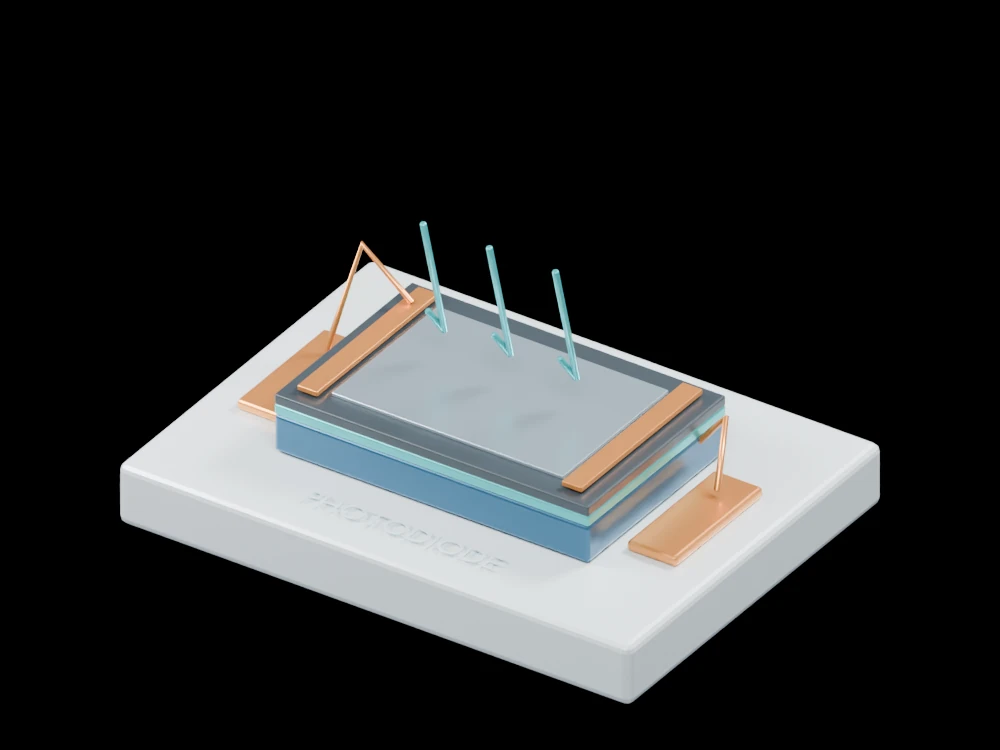
An exposed optical window and enlarged semiconductor layers show the path from incident light to an electrical connection. The assembly separates the sensing surface from its package.
Inside the assembly
The layered sensor sits on a ceramic base beneath a clear window. Two bond wires connect opposite contacts to external pads. Three teal arrows identify the incoming-light direction. Layer thicknesses and the visible junction region are explanatory rather than fabrication dimensions.
Scientific explanation
Within its linear operating range, a photodiode's light-generated current is approximately its responsivity multiplied by incident optical power. Responsivity depends on wavelength. Dark current and the readout circuit must be accounted for when recovering small signals.
- Iph
- Photocurrent attributable to light (A)
- Rλ
- Responsivity at the chosen wavelength (A/W)
- Popt
- Optical power incident on the active area (W)
Linear response at a specified wavelength and bias, with no saturation. The model supplies no measured responsivity or noise floor.
Explore the model
- Follow the arrows through the optical window.
- Identify the active layers beneath the surface.
- Trace both wires to their package terminals.
From geometry to engineering
Select a detector for the wavelength and bandwidth, design a low-noise readout and measure dark offset, response and saturation.