


Below the column: a four-pile foundation assembly
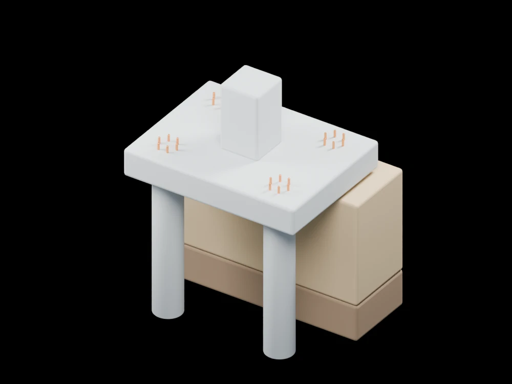
A soil cutaway exposes the path from a column through its pile cap to deeper supports. The model emphasises the arrangement of the foundation rather than a particular ground investigation.
Inside the assembly
Four cylindrical piles support a square cap and a short column. Reinforcement is indicated at the cap and pile heads. Two soil layers remain behind the assembly, leaving the front piles visible down to their toes. These layers illustrate ground stratification without assigning material properties.
Scientific explanation
Axial pile resistance can develop along the shaft and at the toe. A basic component model adds those contributions; their mobilisation depends on soil behaviour and settlement. Group interaction and negative skin friction need separate treatment.
- Qres
- Combined nominal resistance in the simplified component model (N)
- Qshaft, Qtoe
- Shaft and toe resistance contributions (N)
Single-pile component description, excluding pile self-weight in the displayed balance. No allowable load or group efficiency is assigned.
Explore the model
- Follow the column load path into the pile cap.
- Compare the exposed shafts with the two soil layers.
- Rotate behind the cap to locate all four pile heads.
From geometry to engineering
A foundation study needs a ground investigation, load cases, settlement criteria and installation method, followed by appropriate analysis and load testing.