


Separating a slurry with a plate-and-frame filter press
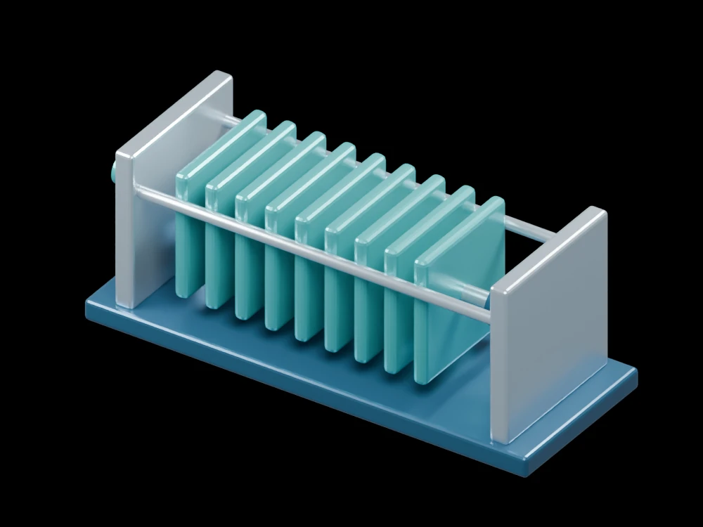
The repeated plates and visible cloth faces reveal how a filter press creates a large filtering area in a compact assembly. The tie rails and pressing mechanism show how the stack is supported.
Inside the assembly
Nine teal plates stand between end supports on a common skid. Pale faces indicate filter cloth, and coloured corner ports identify the manifold positions. A hydraulic ram and central press member represent clamping. Plate spacing is opened for inspection rather than shown as a sealed operating configuration.
Scientific explanation
Pressure drives liquid through a porous medium while solids accumulate as a cake. In a simple resistance model, flux increases with pressure difference and decreases with liquid viscosity and total medium-plus-cake resistance. As the cake grows, its resistance can change substantially.
- J
- Filtrate volume flux per filter area (m/s)
- ΔP, μ
- Pressure difference (Pa) and dynamic viscosity (Pa·s)
- Rm, Rc
- Medium and cake hydraulic resistances (1/m)
Darcy-type laminar filtration. Cake compressibility and changing resistance need process data; the model does not assign a filtration rate.
Explore the model
- Compare each plate with its visible cloth face.
- Trace the tie rails through the plate stack.
- Locate the feed connection and the pressing mechanism.
From geometry to engineering
Test the slurry to determine cake behaviour and filtrate quality before selecting cloth, filter area, cycle pressure and discharge method.