


Two windings, one magnetic path: inside a transformer
The open assembly puts the windings and laminated core in view. Orbit around the model to follow the continuous core through both coils and compare the separate sets of terminals.
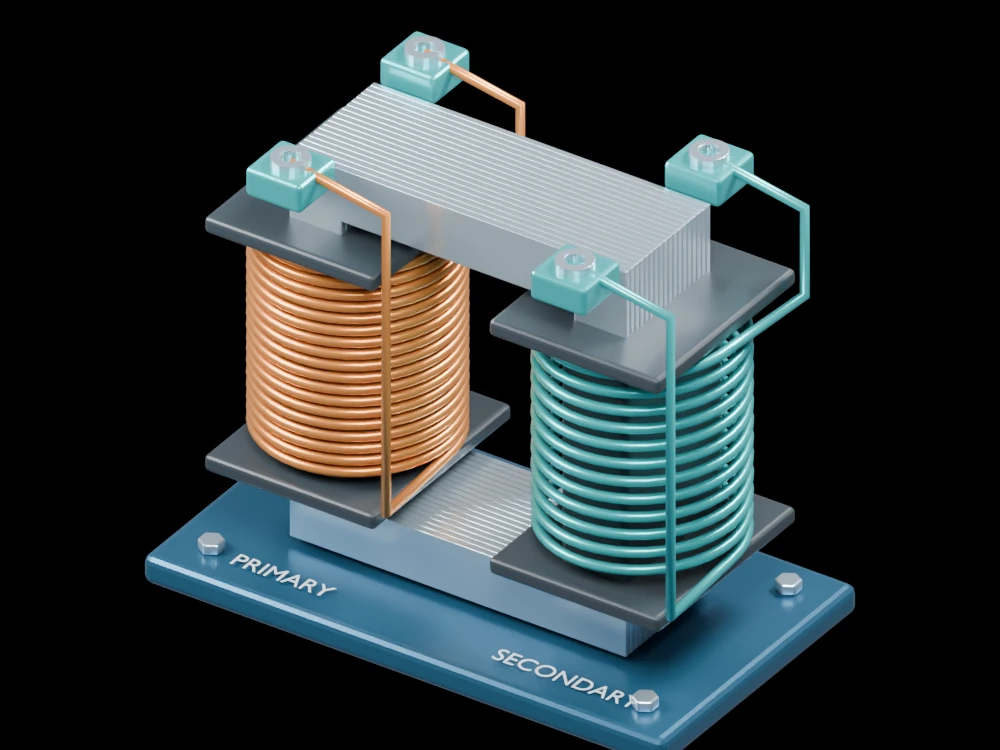
Inside the assembly
Thin steel-coloured sheets form two limbs joined by upper and lower yokes. Copper and teal windings surround separate insulating bobbins. The mounting plate and four terminals make the electrical connections distinct from the magnetic structure. Visible turns are illustrative.
Scientific explanation
An alternating primary voltage produces changing magnetic flux. Flux linking the secondary induces a voltage proportional to its turn count. In an ideal transformer, the voltage ratio equals the turns ratio; current ratios are inverse when power is conserved. A steady DC input does not provide continuous transformer action.
- V₁, V₂
- Primary and secondary RMS voltages (V)
- N₁, N₂
- Primary and secondary winding turns
Ideal coupling, negligible winding resistance, core loss and leakage flux. No voltage, insulation or power rating is assigned to this conceptual assembly.
Explore the model
- Follow the closed laminated path through the two bobbins.
- Compare the winding ends with their separate terminals.
- Look between the coils to see the magnetic window.
From geometry to engineering
A real design requires a core material, operating frequency, allowable flux density, conductor sizing, thermal analysis and verified insulation clearances.