


Concrete and reinforcement: inside a beam cage
Removing the front portion of a beam reveals its longitudinal bars and repeated links. The cutaway helps distinguish the reinforcement cage from the concrete surrounding it.
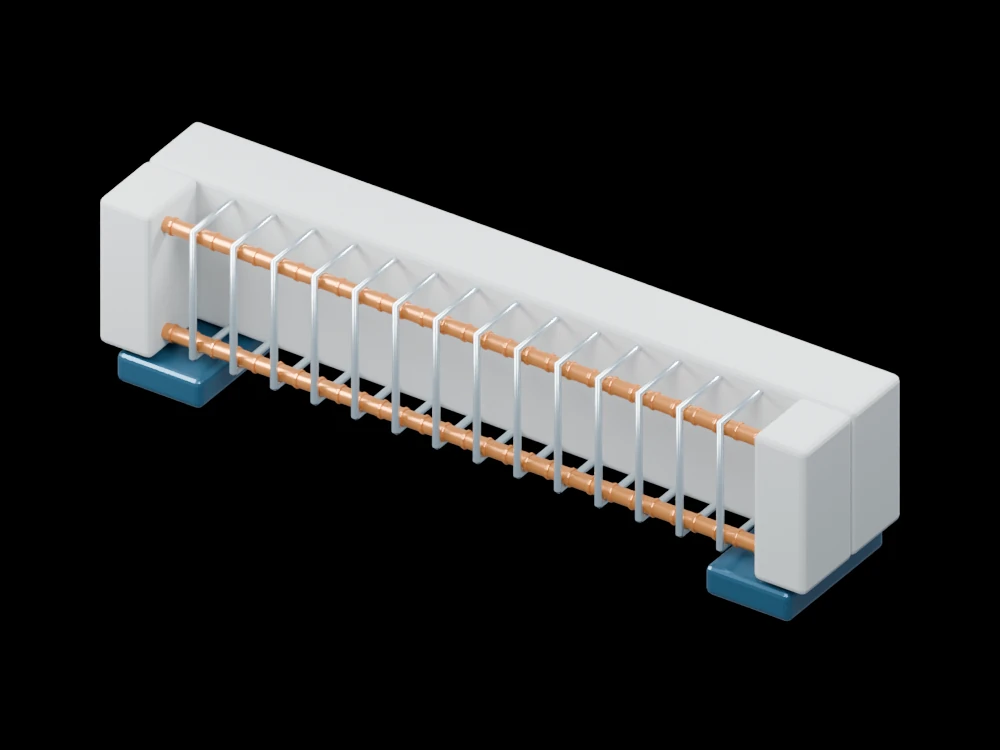
Inside the assembly
Four ribbed longitudinal bars pass through a series of closed stirrups. Concrete remains along the rear face and at the ends, leaving the cage visible between two supports. The bars and links are enlarged for legibility; displayed cover and spacing are not a construction schedule.
Scientific explanation
Under a simple sagging-bending idealisation, compression near the upper part of a section balances tension below. The separated resultants form a couple that resists bending. The relation M = Tz expresses equilibrium; it does not itself determine steel area or concrete capacity.
- C, T
- Compression and tension resultants (N)
- z
- Distance between the resultants (m)
- M
- Resisted bending moment (N·m)
Pure bending with negligible axial force for this explanation. Real reinforcement design also considers cracking, shear, anchorage and durability.
Explore the model
- Distinguish the long bars from the transverse stirrups.
- Inspect the concrete remaining at the end sections.
- Compare the cage location with the outer beam envelope.
From geometry to engineering
A design requires material strengths, loads, span and an applicable design standard. Section analysis and detailing are separate from this educational cutaway.