


Holding a change in level: a cantilever retaining wall
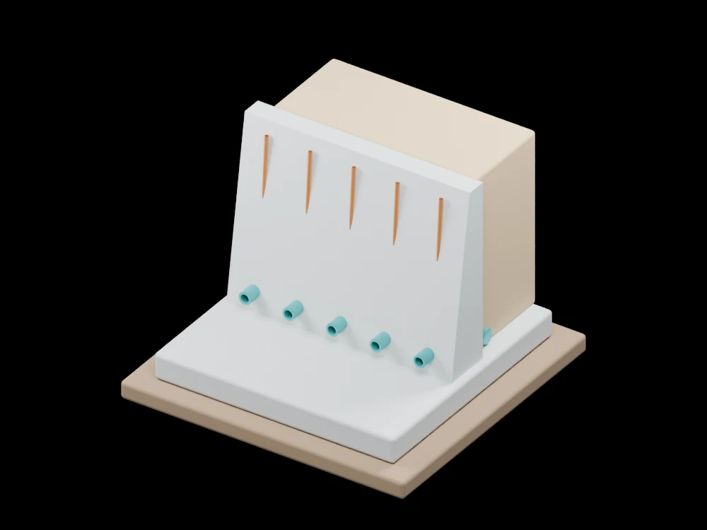
The wall, footing and backfill are separated clearly so their relationship can be explored from both sides. Drain openings make the water-management path visible.
Inside the assembly
A tapered stem rises from a wide base slab, with a soil block behind it. Reinforcement segments illustrate continuity into the stem. Four weep outlets and a collector represent drainage features. The model exposes parts of the arrangement that would normally be hidden by soil.
Scientific explanation
For a smooth vertical wall with level, dry, cohesionless backfill at an active state, Rankine theory gives an earth-pressure coefficient from the soil friction angle. Integrating the triangular pressure distribution gives a resultant proportional to the square of retained height.
- Ka, φ
- Active coefficient and soil friction angle
- γ, H
- Soil unit weight (N/m³) and retained height (m)
- Pa
- Active thrust per unit wall length (N/m)
Ideal active conditions with no cohesion, surcharge or water pressure. A restrained wall or saturated backfill requires different loading considerations.
Explore the model
- Identify the heel and toe portions of the footing.
- Follow the drainage outlets through the stem.
- Compare the backfill height with the tapered wall section.
From geometry to engineering
Check soil and groundwater conditions, drainage reliability, sliding, overturning, bearing and structural resistance before producing a buildable design.