


Alternating ions: the sodium chloride unit cell
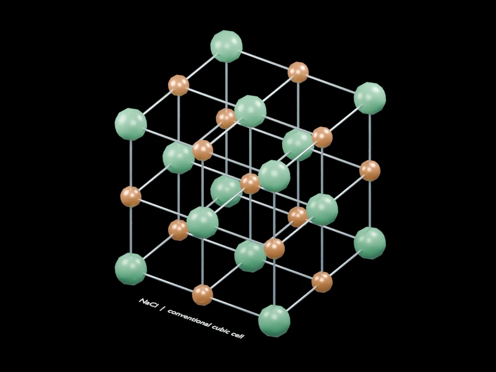
Two sphere sizes and colours reveal the alternating sites of a rock-salt lattice. The cube outline makes boundary sharing visible when counting the contents of a unit cell.
Inside the assembly
Green chloride markers occupy corners and face centres; smaller copper sodium markers occupy edge centres and the body centre. Thin rods identify nearest-neighbour spacings, not covalent bonds. Whole markers are drawn even at boundaries, where a real unit-cell count includes only the appropriate shared fraction.
Scientific explanation
In the conventional rock-salt cell, shared corner and face-centre contributions sum to four chloride ions. Edge-centre and body-centre contributions sum to four sodium ions. Each ion has six nearest neighbours of the opposite species in the extended lattice.
- ⅛, ½, ¼
- Cell shares of corner, face and edge sites
- 4:4
- Four NaCl formula units per conventional cell
Ideal rock-salt lattice. Sphere radii, rod thicknesses and lattice scale are illustrative; exposed boundary sites do not show all neighbours outside this cell.
Explore the model
- Locate the body-centre ion and its six nearest neighbours.
- Distinguish corner, face-centre and edge-centre sites.
- Count fractional site contributions rather than all displayed spheres as whole ions.
From geometry to engineering
Replicate the cell to observe extended coordination, then compare lattice geometry with measured spacing and diffraction data.