


Two flow paths inside a shell-and-tube heat exchanger
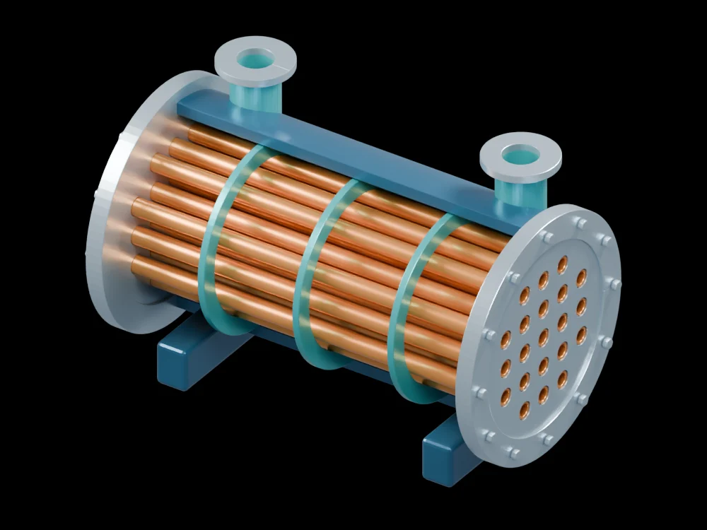
Removing part of the shell reveals the tube bundle and its supports. The assembly helps distinguish the space inside each tube from the surrounding shell-side volume.
Inside the assembly
Individual copper tubes pass through perforated tube sheets. A blue shell cutaway exposes the bundle, support rings and two nozzles. Look along the axis to see the tube bores, then orbit to compare the tube sheets with the intermediate support rings. The rings are structural display features, not a specified flow-baffle arrangement.
Scientific explanation
Thermal energy crosses the tube walls while the two fluids remain separate. For a simple steady exchanger, heat duty can be related to area, an overall transfer coefficient and the log-mean temperature difference. The temperature differences refer to corresponding ends of the chosen flow arrangement.
- Q̇
- Heat-transfer rate (W)
- U, A
- Overall coefficient (W/m²·K) and its matching reference area (m²)
- ΔT₁, ΔT₂
- Positive hot-to-cold temperature differences at the two ends (K)
Steady ideal parallel or counter flow with approximately constant U. Equal end differences use their common value; multipass arrangements may need a correction factor.
Explore the model
- Look into the tube ends to distinguish the bores from the surrounding tube sheet.
- Follow one tube through the open shell to the opposite end.
- Find the shell-side nozzles and compare their space with the inside of the tubes.
From geometry to engineering
Thermal sizing needs fluid properties, flow rates, temperatures and fouling allowances. Pressure loss, tube vibration, pressure containment and fabrication details would need separate engineering work.