


The slider–crank: connecting rotation and translation
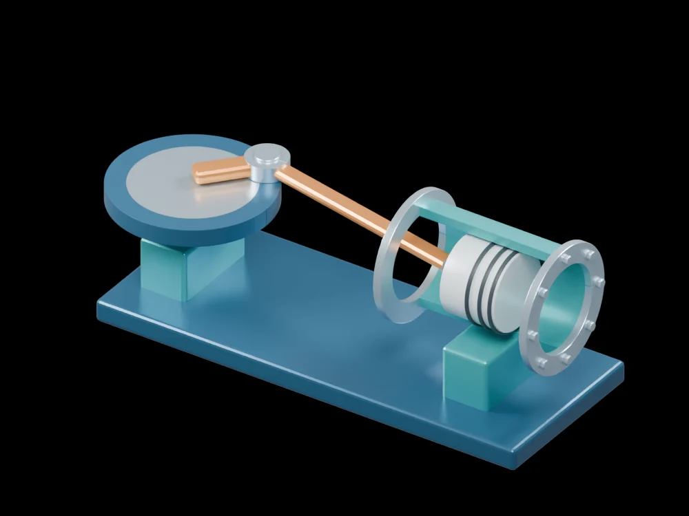
A flywheel, connecting rod and piston form a recognisable path between rotary and linear motion. This open assembly holds the mechanism at one pose so its joints and line of travel remain visible.
Inside the assembly
The crank pin is offset from the flywheel axis. A copper connecting rod joins that pin to the piston inside an open cylinder barrel. Support blocks and a common base make the two main axes visible. Orbit the model to see the pin connections that can be hidden in a flat diagram.
Scientific explanation
For an in-line mechanism, the slider position follows from the right triangle formed by the connecting rod and the crank offset. The expression below adds the crank projection to the rod projection. The distance between the two dead-centre positions is twice the crank radius. Constant crank speed does not imply constant slider speed.
- x
- Slider position measured from the crank centre along the slider axis
- r, l
- Crank radius and connecting-rod length, in the same units
- θ
- Crank angle measured from the slider axis
Rigid links, ideal pin joints, no slider offset and l greater than r. This is a geometric relation, not a dynamic simulation.
Explore the model
- Find the crank centre and the separate, offset crank pin.
- Trace the connecting rod to the piston pin inside the barrel.
- Compare the slider axis with the crank plane and imagine the two dead-centre positions.
From geometry to engineering
Velocity and acceleration follow by differentiating position with respect to time. Predicting forces additionally needs link masses, inertia, friction and the applied load; none is encoded by the display pose.