


From a winding to linear motion: the solenoid actuator
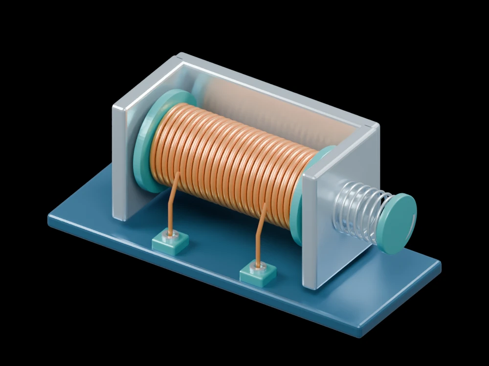
A helical coil surrounds a sliding steel plunger. The open assembly reveals the coil former, return frame and spring so the magnetic and mechanical parts can be inspected separately.
Inside the assembly
Copper turns wrap a dark insulating tube between teal flanges. A steel return frame joins the ends behind the winding. The plunger extends through one end beside an exposed return spring; the fixed pole lies at the other end. This is a single static position.
Scientific explanation
Current in a solenoid creates an axial magnetic field. For a long air-core winding, the central field is approximately proportional to turns per unit length and current. An iron-core actuator changes that field through its material and air-gap geometry. The air-core relation is a starting point, not a prediction of this actuator’s force.
- B
- Approximate central field of a long air-core solenoid (T)
- μ₀
- Permeability of free space (H/m)
- N, l, I
- Turns, winding length (m) and current (A)
The equation assumes a long air-core coil away from its ends. Iron saturation, leakage, spring loading and the moving air gap require a separate actuator model.
References
OpenStax · Solenoids and toroidsExplore the model
- Follow the winding around the insulating former.
- Identify the fixed pole and the projecting plunger.
- Compare the spring and return frame with the winding’s electrical terminals.
From geometry to engineering
Predicting travel and pull force needs a magnetic circuit or field solution, material data, spring stiffness, friction and a thermal duty cycle.