


Mixing and reaction: a jacketed stirred tank
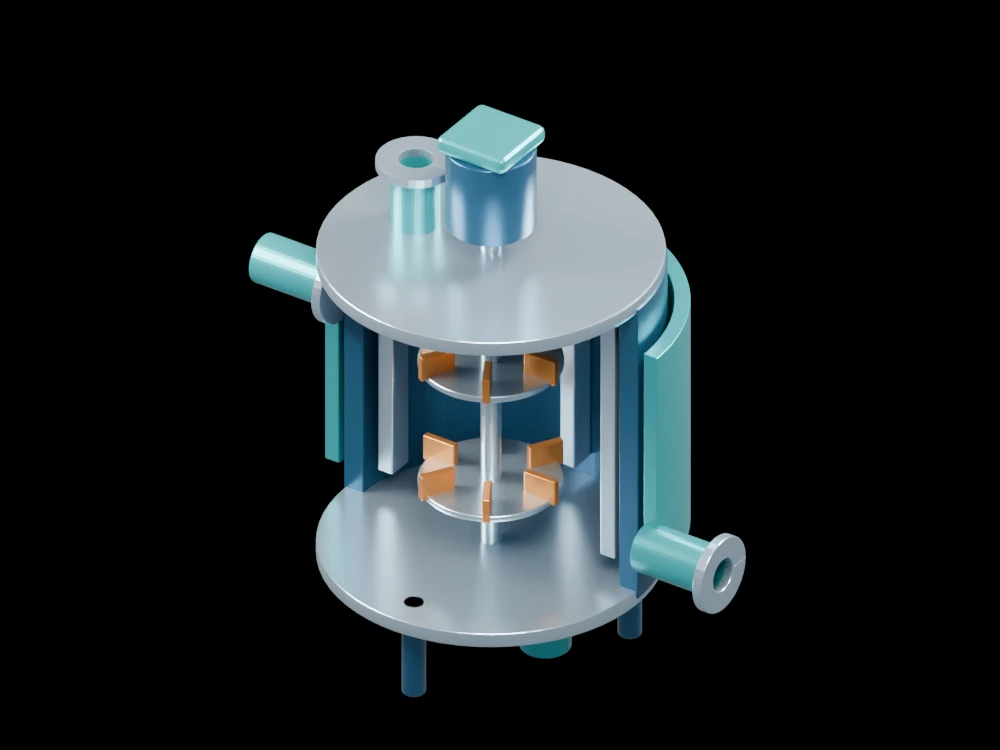
Removing part of the vessel and jacket exposes the two impellers, shaft and baffles. The assembly connects the mechanical arrangement to a basic continuous-reactor balance.
Inside the assembly
Two radial impellers share a vertical shaft driven from above. Baffles remain along the rear wall, and an outer half-jacket shows the space used for heating or cooling. Feed, product and jacket connections are separated around the vessel. The impellers are held at a fixed pose and no fluid motion is simulated.
Scientific explanation
For an ideal well-mixed continuous reactor at steady state, inlet molar flow minus outlet molar flow plus reaction generation is zero for each species. The outlet composition equals the tank composition in this idealisation. Mixing hardware alone does not prove that a real tank achieves perfect mixing.
- FA,in, FA,out
- Species A inlet and outlet molar flow (mol/s)
- rA
- Net volumetric formation rate of A (mol/m³·s), negative for consumption
- V
- Mixed reacting volume (m³)
Steady, spatially uniform composition and temperature for this ideal balance. Heat transfer, kinetics and mixing time are unspecified.
Explore the model
- Trace the shaft from the drive to both impellers.
- Compare stationary baffles with the rotating blade arrangement.
- Locate the two jacket ports outside the reacting volume.
From geometry to engineering
Select reaction kinetics and thermal conditions, then assess mixing, power demand, heat removal and containment for the intended process.