


Triangles over a span: following a truss bridge load path
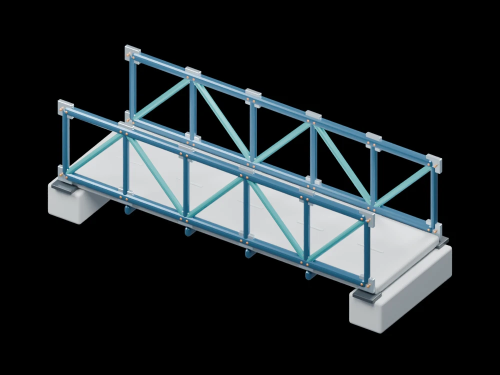
An open bridge assembly reveals how the deck, cross members and two side trusses relate to their end supports. Repeated triangular panels keep the structural arrangement readable.
Inside the assembly
Five bays run between two abutments. Blue chords and teal diagonals meet at gusset plates, while transverse members support the deck. Bearings separate the truss ends from the supporting concrete. Fasteners and gussets are shown for orientation; their dimensions do not represent a connection design.
Scientific explanation
A stationary structure balances external forces and moments. In an ideal pin-jointed truss with loads applied at joints, individual members carry axial forces. Joint equilibrium can then resolve tension and compression, starting where sufficiently few member forces are unknown.
- Fx, Fy
- Force components in the chosen plane (N)
- M
- Moment about a selected point (N·m)
Ideal planar statics. The displayed deck and connections introduce behaviour beyond a simple pin-jointed truss model.
Explore the model
- Trace the deck towards the cross members and side trusses.
- Identify the top and bottom chords in each bay.
- Inspect the bearings at both abutments.
From geometry to engineering
Define the span, loading, material and support conditions before checking member forces, buckling, deflection and connection resistance.