

Mechanical research · Research insights
Printed lattices strengthen turbine cooling in controlled rig tests
Diamond and gyroid cooling lattices were tested against film cooling in 2026. Learn what improved coolant coverage means for a turbine blade.
A turbine blade needs to extract energy from a hot gas while keeping its own material within a workable temperature range. Cooling passages and surface openings compete for a limited supply of cooling air. Recent research explores whether a carefully shaped internal lattice can distribute that air more effectively.
Latest breakthrough
A 2026 International Journal of Heat and Mass Transfer paper compares Diamond and Gyroid triply periodic minimal-surface lattices using experiments and large-eddy simulations. Pressure-sensitive-paint measurements assessed downstream cooling coverage. At high injection ratios, the reported area-averaged adiabatic cooling effectiveness reached up to six times the film-cooling baseline for Diamond and four times for Gyroid. Lower coolant pressure drops were also reported. These are rig-specific cooling measures, not sixfold improvements in turbine efficiency. The work shows how the internal flow geometry can influence the protective film formed outside the wall.
Cheng and colleagues. International Journal of Heat and Mass Transfer (2026). Read the original study.
How the method works
The study compares two lattice geometries through physical tests and large-eddy simulations, which resolve important larger turbulent flow structures while modelling smaller effects. Pressure-sensitive-paint measurements assess downstream cooling coverage in the experimental method. Adiabatic cooling effectiveness is a surface-protection measure under the test's thermal framework, not the overall efficiency of a turbine. Comparing it with pressure loss addresses a key trade-off: moving coolant costs pressure as well as providing protection. Reported gains at high injection ratios should remain attached to that baseline and operating range.
A simple analogy
A protective curtain of air works differently depending on how evenly it covers the surface and how hard the supply system must push. Lattice geometry can influence both features of a cooling flow. The analogy captures coverage and effort, but hot turbulent turbine flows require measurements and simulations far beyond the behaviour of a simple curtain.
A lattice is a flow distributor
Picture cooling air dividing around curved internal surfaces and rejoining through many routes. The arrangement changes how evenly it emerges and how quickly it mixes with the main flow. An effective cooling design must balance coverage with the pressure needed to move the coolant. A geometry that performs well on only one of those measures may be unattractive once included in a complete engine.
Why the result deserves attention
Our interpretation is that the study gives additive manufacturing a specific engineering purpose: controlling flow topology rather than merely producing an unusual shape. Better protection could eventually support longer component life or a different allocation of cooling air. Those benefits matter for power generation and aviation, but they require system-level evidence that includes material durability, manufacturing variability and operating conditions.
From a test surface to a working blade
The paper combines measured cooling behaviour with flow simulation. It does not certify a flight component. Rotating loads, oxidation, blocked passages and inspection access remain practical questions. The reported comparison also depends on the baseline and injection conditions. A reader should keep the experimental cooling metric separate from fuel consumption and service-life predictions. The balance between heat removal and flow resistance also appears in topology-based heat-exchanger design, studied through a different geometry and numerical method.
Locate the parts that need protection
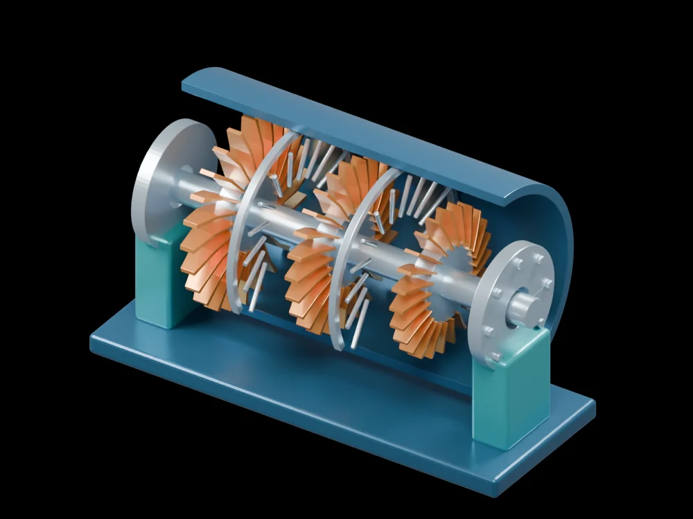
Open the axial-turbine assembly and distinguish the rotor blades from the stationary guide-vane rows. Follow the shaft and inspect the cutaway casing. These parts provide the larger machine context for the cooling question. The gallery model does not include the paper's internal TPMS geometry, so it should be used to understand placement and function rather than to inspect a printable cooling design.
Related articles
 A numerical design twists exchanger walls to improve heat transfer
 A superalloy’s oxide layer becomes a lubricant at extreme temperaturesHydrogen can damage hot turbine alloys through a hidden chemical reactionCooling channels built with the electronics remove heat closer to its sourcePrinted ceramic coatings reflect heat from curved metal surfacesA liquid-metal cooling elastomer changes shape to improve thermal contactA structured water film suppresses boiling bubbles while cooling hot airflowHeat drives a shape-memory cooling cycle in a small prototypeX-rays catch crystals turning while a turbine alloy is laser-remelted
 An accordion-inspired pump recreates complex flow waveformsA stretchable fibre becomes a pump that can be woven into clothingA soft pump runs on energy collected by a triboelectric generatorA soft pump moves liquid without a rotating impeller
 A pilot heat pump reuses distillation heat and reveals a trade-offPhysics-guided AI tracks pump cavitation as flow conditions change
 Gearbox vibrations reveal clues to efficiency during operation
 A modular robot arm succeeds in 91.67% of 240 test trials
 A configurable joint reveals how small gaps turn motion into impacts