

Mechanical research · Research insights
A numerical design twists exchanger walls to improve heat transfer
A 2026 numerical study redesigns both fluid paths in a heat exchanger. Explore the trade-off between better heat transfer and pumping effort.
In a shell-and-tube heat exchanger, the two fluids must exchange heat while remaining separated. Straight tubes and baffles make that arrangement practical, but they also constrain the paths available to the fluids. A new design study asks what happens when the separating structure itself becomes an optimisation variable.
Latest breakthrough
The 2026 International Communications in Heat and Mass Transfer paper uses a density-based topology method to represent hot fluid, cold fluid and a solid wall in a common design domain. It balances heat transfer against flow dissipation and numerically evaluates the resulting configuration over a range of Reynolds numbers. The proposed twisted, perforated walls improve the authors' thermal-hydraulic performance criteria on both sides relative to their conventional reference. This is numerical design evidence. The reported performance-criterion gains should not be read as measured energy savings from an installed industrial exchanger.
Wang and colleagues. International Communications in Heat and Mass Transfer (2026). Read the original study.
How the method works
Topology optimisation searches for where material and flow regions should be placed within an allowed design space. The density-based formulation represents hot fluid, cold fluid and the separating solid, while balancing heat transfer against flow dissipation. Numerical evaluation across Reynolds numbers examines how the design responds as the flow regime changes. Reynolds number compares inertial and viscous effects; it is not a heat-transfer score. The resulting performance criteria support a computational design comparison, while manufacturing constraints, fouling and experimental performance would require additional investigation.
A simple analogy
Designing a good passage between two busy areas requires deciding where routes and separating walls should go, not merely widening an existing doorway. Topology design asks a comparable spatial question for fluids and heat. The software does not escape physical constraints, and a digitally attractive layout is not automatically easy to manufacture, clean or operate.
The boundary layer is part of the design
Fluid close to a wall behaves differently from fluid moving through the centre of a passage. Heat must pass through that near-wall region. Redirecting the flow can renew fluid at the surface, but each turn can also consume pressure. The design challenge is therefore not simply to create more surface area: it is to make that area useful without demanding excessive pumping power.
A different question for optimisation
The appealing idea is to optimise the two flow paths together. Improving one side while worsening the other can leave the overall equipment less useful. Our interpretation is that this approach could help screen unconventional geometries before prototype manufacture. It makes the design process more explicit about competing objectives, which is valuable in heat recovery, process cooling and compact equipment development.
What a practical design still needs
Manufacturing access, cleaning, fouling, corrosion and pressure containment can all determine whether an elegant numerical geometry is usable. The optimisation assumptions and reference design also affect the size of the reported improvement. Physical prototypes, pressure tests and long-duration fouling studies would be needed before making claims about cost or environmental benefit in service. Experimental work on printed lattices for turbine cooling explores another way geometry can alter heat transfer and pressure loss.
Compare the conventional geometry in 3D
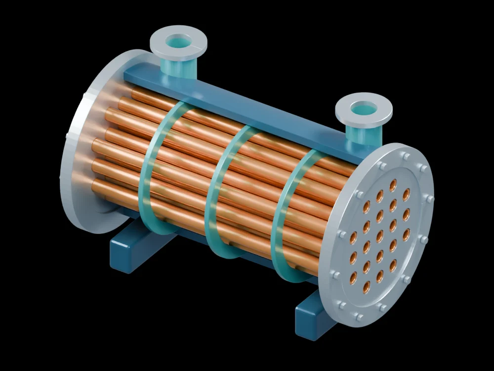
The gallery exchanger exposes individual hollow tubes, tube sheets, shell nozzles and the surrounding shell. Trace the two separate routes and identify the wall through which heat must travel. That conventional arrangement is the starting point for understanding the paper's design question. The supplied model is not the optimised research geometry and does not contain a calculated heat-transfer rating.
Related articles
 Printed lattices strengthen turbine cooling in controlled rig tests
 A pilot heat pump reuses distillation heat and reveals a trade-off
 An accordion-inspired pump recreates complex flow waveformsA stretchable fibre becomes a pump that can be woven into clothingA superalloy’s oxide layer becomes a lubricant at extreme temperaturesHydrogen can damage hot turbine alloys through a hidden chemical reaction
 Cooling channels built with the electronics remove heat closer to its sourcePrinted ceramic coatings reflect heat from curved metal surfacesA soft pump runs on energy collected by a triboelectric generatorA liquid-metal cooling elastomer changes shape to improve thermal contactA soft pump moves liquid without a rotating impellerA structured water film suppresses boiling bubbles while cooling hot airflowHeat drives a shape-memory cooling cycle in a small prototypeX-rays catch crystals turning while a turbine alloy is laser-remeltedPhysics-guided AI tracks pump cavitation as flow conditions change
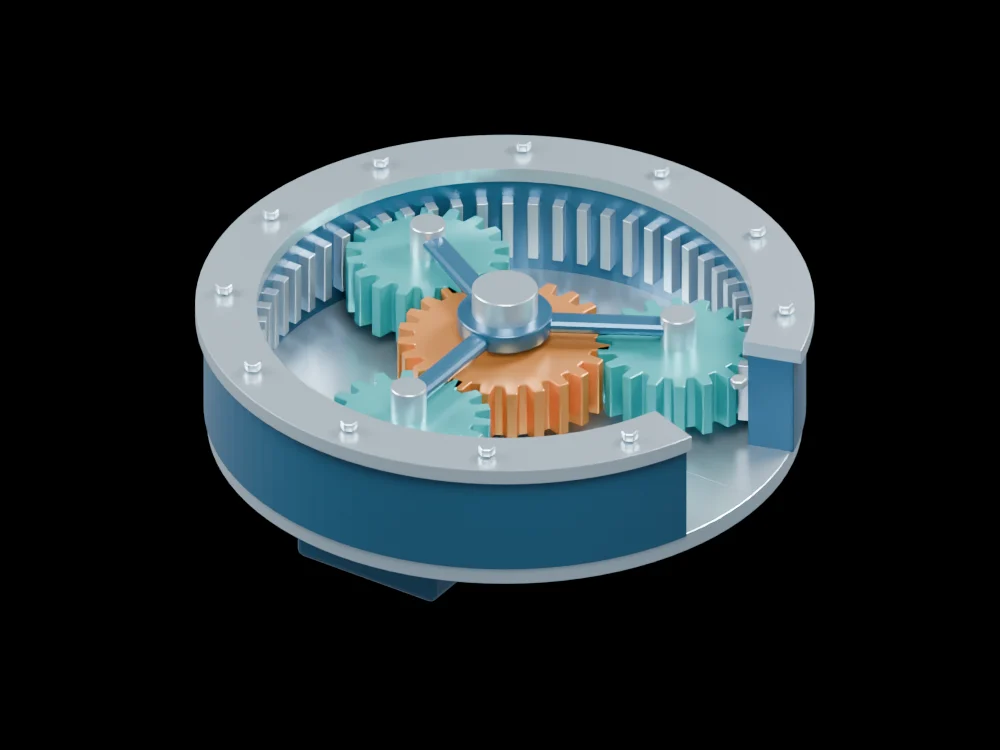 Gearbox vibrations reveal clues to efficiency during operation
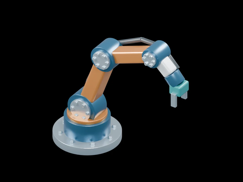 A modular robot arm succeeds in 91.67% of 240 test trials
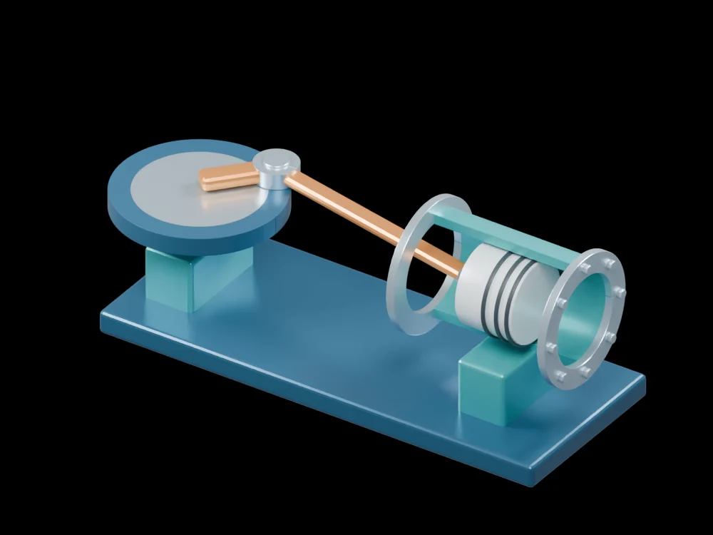 A configurable joint reveals how small gaps turn motion into impacts