

Mechanical research · Research insights
A configurable joint reveals how small gaps turn motion into impacts
A 2026 experiment examines worn and non-circular joints in a slider–crank. Discover why clearance shape and assembly orientation both matter.
The familiar slider–crank diagram connects rotation to reciprocating motion with perfectly fitted joints. Real bearings need clearance, and wear rarely preserves an ideal circle. The resulting impacts can change the motion of the piston even when the nominal crank radius and connecting-rod length remain unchanged.
Latest breakthrough
A 2026 Nonlinear Dynamics study investigates an offset slider–crank with adjustable joint clearance, non-circular contact profiles and different installation orientations. Researchers measured slider velocity and acceleration and used a curvature-based contact model to interpret the responses. Their results show that increasing clearance and crank speed intensifies impact-dominated behaviour. The useful advance is the combined treatment of clearance shape and assembly angle, supported by a configurable experiment, rather than treating the joint as a circular gap described by one dimension.
Liu and colleagues. Nonlinear Dynamics (2026). Read the original study.
How the method works
A configurable mechanism allows joint clearance, contact shape and installation angle to be investigated rather than treating the clearance as one fixed circular gap. Measurements of slider velocity and acceleration describe motion and how rapidly it changes. A curvature-based contact model then helps interpret when and how the joint surfaces interact. Impacts can introduce sharp acceleration changes that are less apparent in average motion. Comparing measurements with the contact representation provides evidence for the selected configurations, rather than establishing a universal response for all linkages with wear.
A simple analogy
A loose door hinge can move smoothly through part of its travel and then strike its surroundings when the gap changes which surfaces touch. A linkage joint can also alternate between free motion and contact. The door illustration explains why a small gap matters, but a driven slider-crank has different speeds, geometry and inertial forces.
From a kinematic path to a contact problem
In an ideal mechanism, joint centres follow prescribed paths. With clearance, a pin can move within its bearing before contact transmits force. The point of contact depends on the direction of loading and the local surface shape. A small change in orientation can therefore change when contact occurs. Acceleration is especially revealing because an impact may be brief while producing a strong response.
Why this matters outside an engine
The same reasoning applies to reciprocating pumps, compressors and linkage-driven equipment. Our engineering interpretation is that maintenance specifications should consider more than average hole diameter when repeated impacts are a concern. Better representation of worn geometry can help an engineer decide whether vibration comes from the drive, the load or the joint itself. It may also support more realistic digital models for troubleshooting.
A useful result with a defined scope
The experiment does not provide a universal allowable clearance for every mechanism. Load, lubrication, material compliance and operating speed affect contact behaviour. A model that explains a measured response still needs validation for the machine being assessed. The paper is a specialist advance in mechanism dynamics; its evidence does not establish a worldwide popularity ranking or a maintenance interval. The challenge of linking vibration to internal behaviour also appears in operating-state gearbox measurements.
Inspect the joint before following the piston
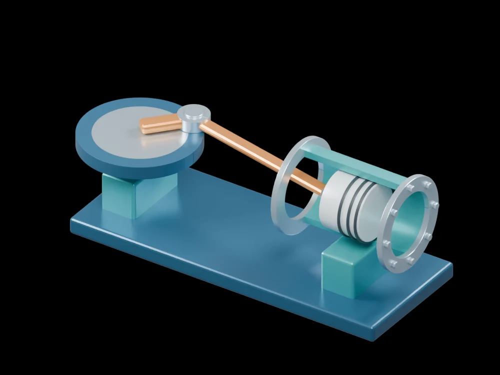
In the gallery, start at the crank and flywheel, then follow the connecting rod to the piston. Look closely at the bearing locations that enforce the linkage geometry. The model deliberately makes the arrangement legible; it does not contain the experimentally varied wear profiles. Use it to understand where a clearance model belongs, rather than to read a manufacturing tolerance from the mesh.
Related articles
 Gearbox vibrations reveal clues to efficiency during operation
 An engineered environment changes a microscopic engine’s power–efficiency trade-offMagnetic measurements expose early fatigue changes in tested metalsChanging the character of noise shifts a microscopic engine’s best operating speedSwitching between unstable modes can stabilise a mechanical oscillator
 Changing a motor's magnetic geometry tackles a narrow noise peak
 An accordion-inspired pump recreates complex flow waveforms
 Dense liquid-metal coils combine soft actuation, sensing and communicationA DNA clutch lets a magnetic nanomotor engage and disengage its rotorElastic electromagnetic mechanisms give small robots muscle-like motionElectric current drives a molecular rotor and changes its conductanceA stretchable fibre becomes a pump that can be woven into clothingNanotextured surfaces help graphite maintain an extremely low-friction contactProjected light assembles and drives reconfigurable microscopic machinesLiquid-metal networks turn a flat elastomer into programmable 3D surfacesMicroscopy reveals which internal features hold a permanent magnet’s directionLight drives microscopic gear trains through patterned metasurfacesA soft pump runs on energy collected by a triboelectric generatorSoft robots steer their shape by combining local electromagnetic vectorsFriction consolidates brittle magnetic powders in a single processing stepA soft robot arm stays bendable while transmitting continuous torqueA soft pump moves liquid without a rotating impeller
 Printed lattices strengthen turbine cooling in controlled rig testsPhysics-guided AI tracks pump cavitation as flow conditions change
 A modular robot arm succeeds in 91.67% of 240 test trials
 A numerical design twists exchanger walls to improve heat transfer