

Electrical research · Research insights
A two-phase buck converter tackles the light-load efficiency problem
A fabricated 6 MHz converter combines two phases with current-sensing and light-load control. Learn why peak efficiency is only part of the story.
Portable electronics spend much of their time doing less than their maximum workload. A voltage regulator that performs well at full load can therefore waste energy during ordinary use. Designing a compact buck converter requires attention to both fast switching and the changing current demanded by its load.
Latest breakthrough
The selected 2026 Microelectronics Journal paper reports a fabricated 6 MHz, two-phase buck converter using adaptive on-time control. A passive sensing network estimates inductor current, and a phase manager coordinates the two switching channels. A zero-crossing detector supports operation at light loads. The prototype, made in a 180 nm BCD process with 120 nH inductors, achieved 89.8% peak efficiency; the authors also report a light-load efficiency improvement against their comparison condition. The important contribution is the combination of control and sensing features in measured hardware, rather than a peak-efficiency number in isolation.
Microelectronics Journal (2026). Read the original study.
How the method works
The converter alternates switching states to reduce a DC voltage, using two phases whose activity is coordinated by a phase manager. Adaptive on-time control adjusts switching behaviour, while a passive sensing network estimates inductor current. At light load, detecting when current crosses zero helps manage operation when the assumptions of heavier-load conduction no longer apply. The fabricated prototype tests these functions together. Peak efficiency reports the best measured ratio under particular conditions; the light-load comparison asks a different question about performance when demand is small.
A simple analogy
Two delivery lanes can share a heavy workload, but keeping both equally active during quiet periods may waste effort. Coordinating their activity can improve light-demand operation. Electrical switching and inductor current are more constrained than delivery traffic, so the analogy explains phase management without providing a substitute for circuit waveforms or stability analysis.
Why two phases can help
A buck stage repeatedly connects and disconnects its input while an inductor and capacitor smooth the delivered energy. Interleaving two channels spreads the switching activity through time. That can reduce ripple and change the component requirements, but it also adds coordination problems. Accurate knowledge of current is especially useful near the point where an inductor stops conducting during part of a cycle.
Compactness brings its own trade-offs
Higher switching frequency can reduce the energy that must be stored in each cycle, allowing smaller passive components. At the same time, switching itself consumes energy. Our interpretation is that the useful advance lies in balancing these competing effects over a realistic load range. A battery-powered product benefits from the efficiency it achieves during actual use, including long periods of low demand.
What still needs a product-level comparison
The prototype's results belong to its voltage range, load conditions and component choices. Board layout, thermal constraints and electromagnetic interference can change the outcome in a finished device. A complete comparison should include transient response and idle consumption as well as efficiency. The paper demonstrates a converter architecture, not a universal replacement for every regulator. At a much larger power level, the solid-state transformer prototype raises related questions about conversion efficiency and operating conditions.
Find the energy-storage elements
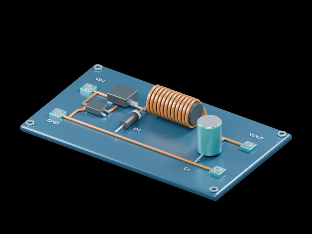
Open the gallery buck converter and identify the MOSFET, freewheel diode, exposed inductor winding and output capacitor. Follow the power terminals into that circuit. The model explains a conventional single-stage arrangement; the research prototype uses a more elaborate two-phase control implementation. The visible assembly is not an electrical design file or a validated high-frequency layout.
Related articles
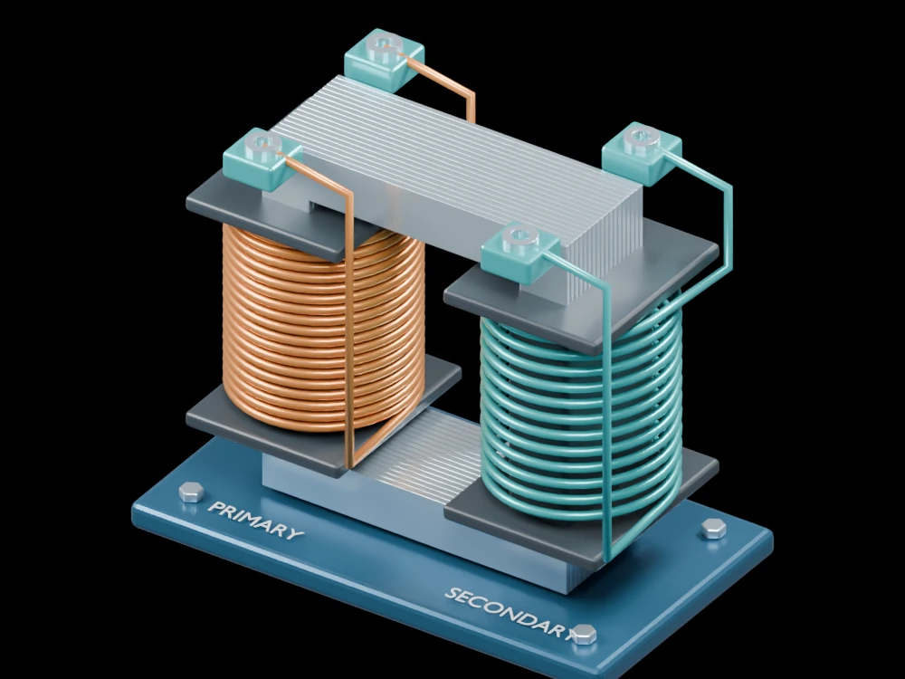 A 100 kW solid-state transformer reaches 98.57% efficiency in testing
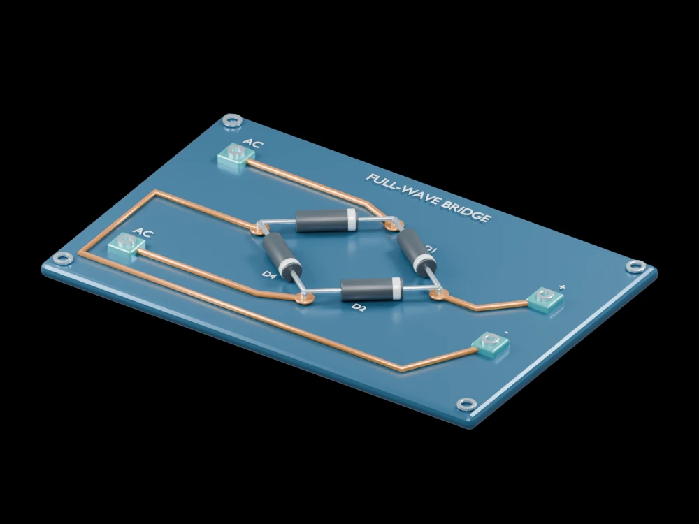 A quantum material rectifies signals from radio to terahertz bands
 Boron arsenide draws heat from working GaN transistorsComplementary GaN logic puts both transistor types on one substrateA magnetic composite tackles eddy-current and hysteresis losses togetherNarrow magnetic domains help an iron-rich ribbon waste less energyMagnetic-domain motion can send energy into the crystal latticeA vibrating resonator helps a DC converter step down voltage efficientlyBuilt-in crystal polarization helps GaN switches withstand higher voltageEngineered interfaces let magnetic particles couple without the usual loss penaltyNanoscale spin rectifiers turn weak radio signals into useful powerA superconducting chip brings full-wave rectification into the coldElemental tellurium turns radio signals into a tunable room-temperature outputTin telluride rectifies signals from megahertz to terahertz without external bias
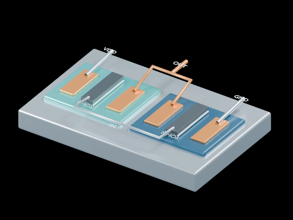 A new gate interface enables 2D inverters with subpicowatt static power
 Circuits stacked below 300°C offer a route to denser chips
 A red micro-LED prototype packs 1,700 pixels into each inch
 Changing a motor's magnetic geometry tackles a narrow noise peak
 Matched motor tests connect higher efficiency with lower heat
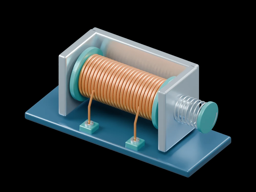 A redesigned magnetic path cuts opening time in a solenoid study