

Electrical research · Research insights
Matched motor tests connect higher efficiency with lower heat
Prototype testing connects induction-motor efficiency with losses, temperature and cost. Learn which findings can guide a real replacement decision.
Motor efficiency becomes meaningful when it is connected to the work a motor actually performs. Two machines with the same rated power can differ in losses, temperature and starting behaviour. A useful comparison therefore looks beyond the efficiency label to the electromagnetic design and the operating duty.
Latest breakthrough
A July 2026 Applied Sciences study compares IE2 and IE4 induction motors with matching rated power and frame size using electromagnetic simulations and prototype measurements. The IE4 design showed lower total losses, reduced torque ripple and a lower steady operating temperature in the reported comparison. Testing followed IEC 60034-2-1 procedures. The authors' economic calculation gave an approximately 0.81-year payback for their representative duty and cost assumptions. That payback is a scenario result, not a promise for another factory. The study's value is the connection between electrical performance, thermal behaviour and a stated economic case.
Suli and colleagues. Applied Sciences (2026). Read the original study.
How the method works
Matching rated power and frame size makes the comparison more informative than comparing two unrelated motors. Electromagnetic simulation explores the field and loss behaviour, while prototype measurements test actual performance using the stated standard procedure. Losses become heat, but electrical loss, torque ripple and temperature are distinct measurements. The economic calculation then translates a performance difference into a payback under assumed use and prices. That final calculation depends on the application: a lightly used motor and a continuously loaded motor need not justify an upgrade in the same period.
A simple analogy
Two appliances can fit the same space and perform the same rated job while wasting different amounts of energy as heat. A fair comparison keeps the job comparable and measures more than the label. Motors also operate across changing speed and load conditions, so the appliance analogy does not turn one test point into a universal savings estimate.
Where the energy goes
The stator creates a rotating magnetic field that induces current in the rotor. Producing useful shaft torque requires current and magnetic flux, both of which bring losses. Friction and ventilation add further demands. Looking at the loss distribution helps an engineer understand why a design change works and whether it is likely to remain useful away from the rated operating point.
An upgrade is an operating decision
Our interpretation is that a replacement decision should start with measured running hours, load distribution and the local electricity tariff. A motor that runs continuously offers a different economic opportunity from an occasionally used spare. Starting requirements and compatibility with the driven machine also matter. The public benefit of higher efficiency comes from actual avoided energy use over service life, including the consequences of manufacturing a replacement.
What the comparison cannot decide for you
The paper evaluates particular designs under specified conditions. It does not establish a universal payback period or justify replacing every serviceable motor immediately. A site-level analysis should account for installation cost, downtime and expected remaining life. Efficiency class is a useful starting point, while a properly bounded comparison supplies the decision evidence. Magnetic design can target other outcomes too, including reduced vibration and noise in a brushed DC motor.
Read the motor through its cutaway
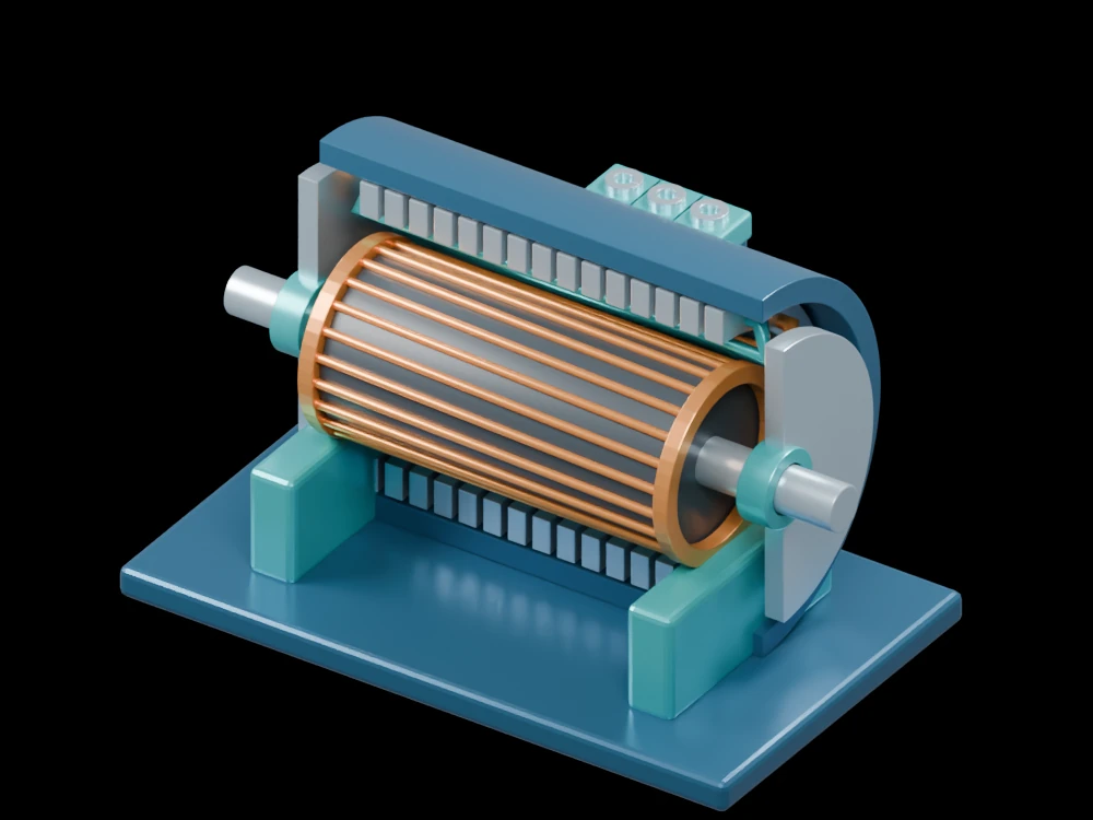
Open the induction-motor model and separate the stationary windings from the rotating squirrel cage. Follow the cage bars into the end rings, then locate the bearings and shaft. These parts help explain where current, magnetic coupling and mechanical support interact. The gallery geometry is educational and carries no tested efficiency-class certification.
Related articles
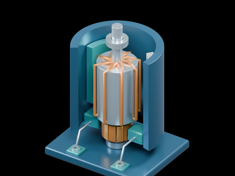 Changing a motor's magnetic geometry tackles a narrow noise peak
 A rotating magnetic field steers crystallisation toward finer soft magnetsAn alloy becomes mechanically strong while remaining magnetically softTiny manufacturing deformations can disturb the magnetic structure of motor steelNanoprecipitates push ductile soft magnets toward two-gigapascal strength
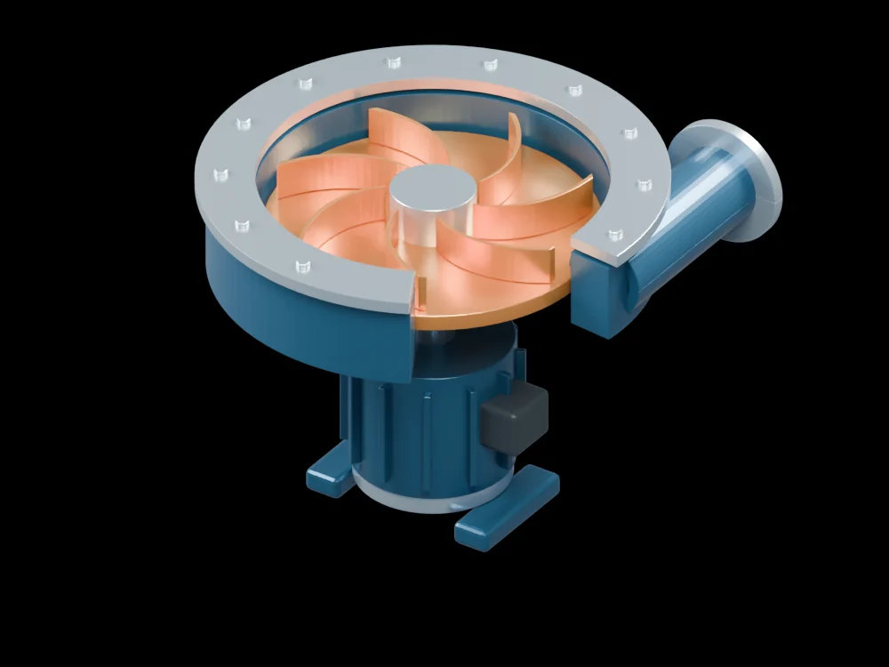 Physics-guided AI tracks pump cavitation as flow conditions changeAn accordion-inspired pump recreates complex flow waveformsA stretchable fibre becomes a pump that can be woven into clothing
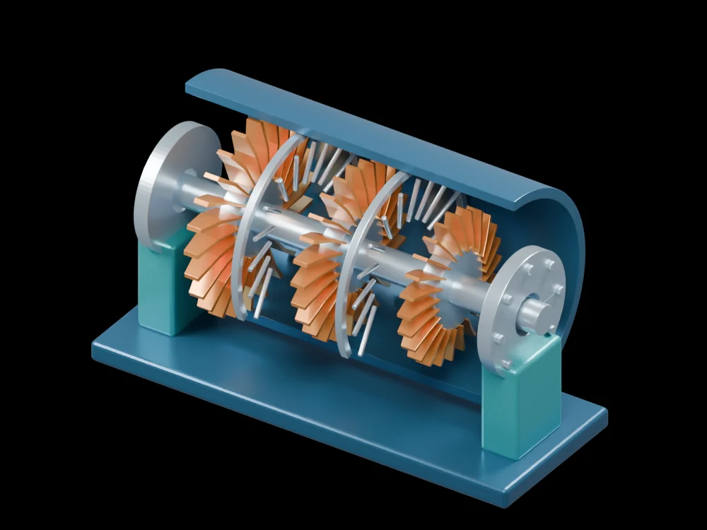 A superalloy’s oxide layer becomes a lubricant at extreme temperaturesHydrogen can damage hot turbine alloys through a hidden chemical reaction
 A magnetic composite tackles eddy-current and hysteresis losses togetherNarrow magnetic domains help an iron-rich ribbon waste less energyMagnetic-domain motion can send energy into the crystal lattice
 Cooling channels built with the electronics remove heat closer to its sourcePrinted ceramic coatings reflect heat from curved metal surfacesA soft pump runs on energy collected by a triboelectric generatorA liquid-metal cooling elastomer changes shape to improve thermal contactEngineered interfaces let magnetic particles couple without the usual loss penaltyA soft pump moves liquid without a rotating impellerA structured water film suppresses boiling bubbles while cooling hot airflowHeat drives a shape-memory cooling cycle in a small prototypeX-rays catch crystals turning while a turbine alloy is laser-remelted
 Gearbox vibrations reveal clues to efficiency during operation
 A quantum material rectifies signals from radio to terahertz bands
 A two-phase buck converter tackles the light-load efficiency problemA 100 kW solid-state transformer reaches 98.57% efficiency in testing
 A redesigned magnetic path cuts opening time in a solenoid study