

Electrical research · Research insights
A 100 kW solid-state transformer reaches 98.57% efficiency in testing
A 100 kW solid-state transformer prototype reported 98.57% full-load efficiency. Explore the magnetic and electronic parts behind that result.
A transformer changes voltage through magnetic coupling. A solid-state transformer adds controlled power-electronic conversion around that function, creating more choices about voltage regulation and power flow. The extra flexibility also creates more opportunities for electrical loss, making the complete architecture important.
Latest breakthrough
A September 2026 Scientific Reports paper proposes a multilevel solid-state transformer for data-centre distribution. Its hybrid cascaded arrangement combines silicon-carbide switches, flying-capacitor stages and isolated conversion. The authors report 98.57% measured full-load efficiency on a 100 kW prototype. They also optimise several competing design objectives, including efficiency, density, cost and stability. A reported improvement in the optimisation algorithm comes from a single run, which the paper itself distinguishes from statistical proof. The hardware measurement is the central evidence; simulated performance at other operating points is a separate result.
Liu and colleagues. Scientific Reports (2026). Read the original study.
How the method works
A solid-state transformer uses controlled switching stages and isolation rather than relying only on a conventional line-frequency magnetic transformer. The study combines a multilevel arrangement with optimisation across competing objectives and reports measurements on a 100 kW prototype. Efficiency compares delivered power with input power at a stated operating point. The full-load measurement is therefore more specific than a claim about every load condition. Optimisation results also need their own evidence: an improved result in one algorithm run is not a statistical demonstration that the method consistently outperforms alternatives.
A simple analogy
Moving goods through several carefully coordinated transfer stations can serve a different purpose from using one direct crossing. Each station adds control, but also losses and complexity. Power-conversion stages similarly need to be judged together. Electrical isolation and switching are not warehouse operations; the comparison only explains why system-level performance cannot be inferred from one component.
Why keep a magnetic stage?
Electronic switches can change the timing and form of electrical power, while a magnetic component can provide voltage transformation and isolation. Combining the two requires attention to switching frequency, insulation, heat removal and unwanted electrical interference. It is helpful to view the equipment as a chain of conversions: a small improvement in one stage can be offset by losses elsewhere.
What the prototype makes worth investigating
For a continuously operating facility, a modest change in losses can accumulate over many hours. Our interpretation is that the most useful next comparison would use a realistic demand profile, including lightly loaded periods and standby operation. Reliability and repairability also deserve weight. A high-efficiency prototype is encouraging, but the best architecture for a particular site depends on the entire distribution system.
Avoid comparing unlike efficiency numbers
The reported figure belongs to the study's hardware and test conditions. It does not establish that every solid-state transformer outperforms every conventional transformer. Cooling auxiliaries, loading and measurement boundaries should be aligned before comparing alternatives. Larger-scale operation and long service life remain different questions from a successful prototype measurement. The importance of efficiency across operating conditions is also visible at a smaller scale in the buck-converter study.
Explore the magnetic foundation
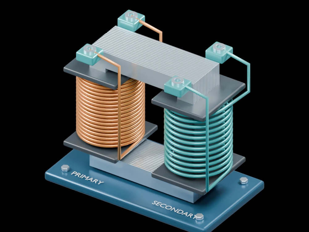
In the gallery transformer, identify the primary and secondary windings and the laminated core that links them. Observe how insulation and terminals keep the circuits physically organised. This conventional model explains the magnetic principle retained within more elaborate conversion systems. It does not reproduce the study's switching topology, power rating or high-voltage insulation design.
Related articles
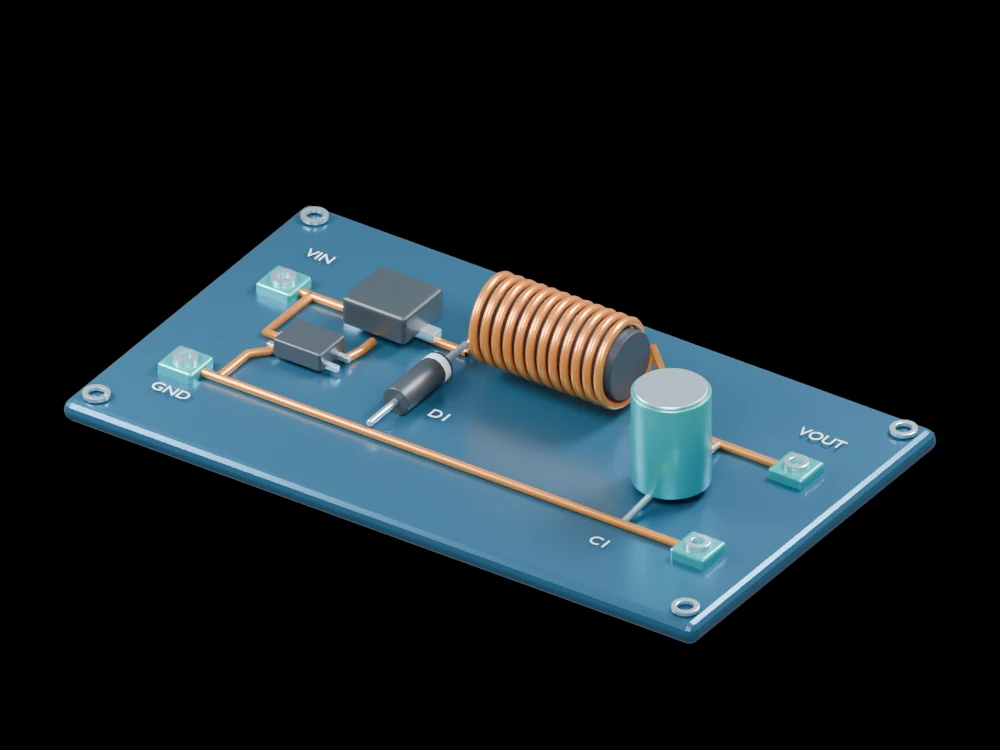 A two-phase buck converter tackles the light-load efficiency problemBoron arsenide draws heat from working GaN transistorsComplementary GaN logic puts both transistor types on one substrateA vibrating resonator helps a DC converter step down voltage efficientlyBuilt-in crystal polarization helps GaN switches withstand higher voltage
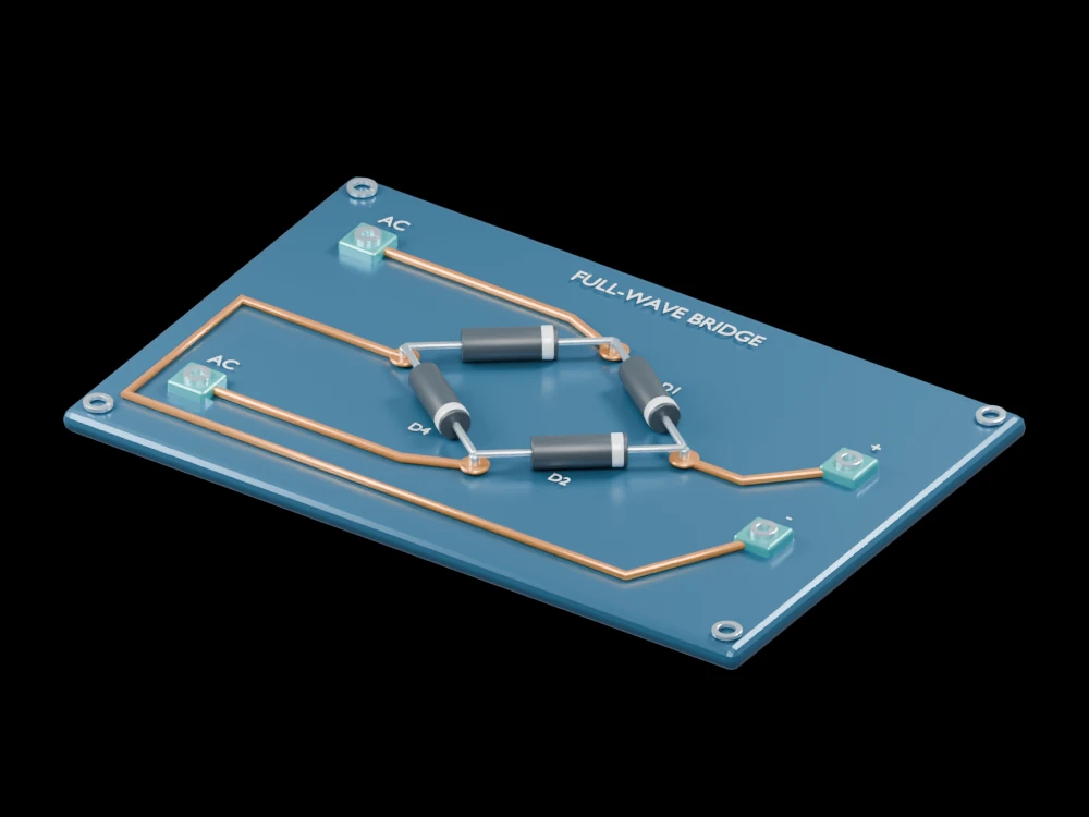 Nanoscale spin rectifiers turn weak radio signals into useful powerA superconducting chip brings full-wave rectification into the coldElemental tellurium turns radio signals into a tunable room-temperature outputTin telluride rectifies signals from megahertz to terahertz without external biasA quantum material rectifies signals from radio to terahertz bands
 A magnetic composite tackles eddy-current and hysteresis losses togetherNarrow magnetic domains help an iron-rich ribbon waste less energyMagnetic-domain motion can send energy into the crystal latticeEngineered interfaces let magnetic particles couple without the usual loss penalty
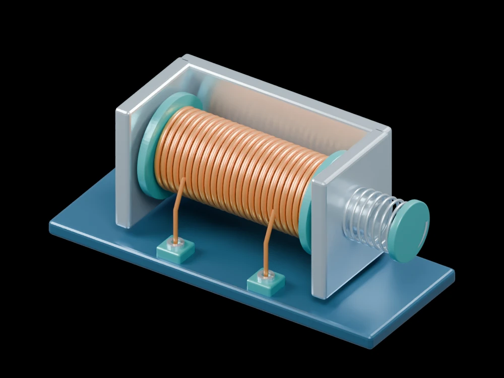 A redesigned magnetic path cuts opening time in a solenoid study
 A rotating magnetic field steers crystallisation toward finer soft magnetsAn alloy becomes mechanically strong while remaining magnetically softTiny manufacturing deformations can disturb the magnetic structure of motor steelNanoprecipitates push ductile soft magnets toward two-gigapascal strength
 An electrically heated foam brings heat inside a catalyst bed
 Changing a motor's magnetic geometry tackles a narrow noise peakMatched motor tests connect higher efficiency with lower heat