

Electrical research · Research insights
Changing a motor's magnetic geometry tackles a narrow noise peak
A 2026 study combines simulation, machine learning and tests to reduce vibration in a blower motor. See how magnet geometry affects torque ripple.
A small brushed DC motor can be mechanically simple and still produce a complicated sound. Some vibration comes from electromagnetic forces changing as the armature turns. Improving acoustic behaviour therefore involves understanding the interaction between magnetic geometry and the mechanical structure, as well as the brushes themselves.
Latest breakthrough
The April 2026 Machines paper studies a twelve-slot, two-pole permanent-magnet brushed motor for automotive blower applications. It combines finite-element modelling, response-surface optimisation, a random-forest predictor and experimental validation. Pole-arc geometry and magnet eccentricity are examined as ways to reduce cogging torque. The reported optimised structure suppresses resonance-related noise near 7,500 Hz and improves the studied motor's vibration behaviour. The advance is a connected design workflow linking electromagnetic quantities to mechanical response, rather than an assumption that a stronger magnet always produces a better motor.
Ren and colleagues. Machines (2026). Read the original study.
How the method works
Finite-element modelling estimates how the magnetic field changes with geometry. Response-surface optimisation and a random-forest predictor help explore relationships between design variables and predicted behaviour, followed by experimental validation. Cogging torque is the position-dependent interaction associated with the magnetic structure, even before considering every effect of the driven load. Its variation can contribute to vibration, which can excite a mechanical resonance and become audible. The method links several physical stages; reducing a simulated magnetic quantity alone would not establish the measured acoustic outcome.
A simple analogy
A repeated push on a swing becomes especially effective near the swing's natural rhythm. Similarly, periodic forces in a motor can excite a particular structural response. Changing the magnetic geometry changes the pattern of those pushes. A real motor has several vibration paths and resonances, so the swing illustrates timing sensitivity rather than all sources of noise.
What cogging torque means
Even without useful load, the magnetic circuit can favour certain rotor positions. As teeth and magnet poles move past one another, magnetic attraction changes. This periodic tendency adds to other torque variations. If a forcing frequency excites a structural resonance, a relatively small disturbance can become a noticeable sound. The speed, housing and supports therefore belong in the explanation.
Why a data model can help design
An engineer may need to evaluate many combinations of dimensions. A predictive model can help screen candidates before detailed analysis or fabrication, provided it is checked against reliable data. Our interpretation is that the method's practical value lies in reducing an expensive search space. Better acoustic comfort in ventilation equipment is a plausible benefit, but it has to be confirmed in the final assembled product.
Geometry is not the whole noise problem
Brush contact, bearings, imbalance and the attached fan can produce additional disturbances. A result for one blower motor does not establish a noise reduction for all brushed motors. Prediction quality also depends on the range of designs used to train and validate the data model. Production variation and endurance testing would be relevant next steps. This focus on vibration complements the induction-motor comparison of losses and temperature, rather than replacing those performance measures.
Inspect the magnetic and mechanical routes
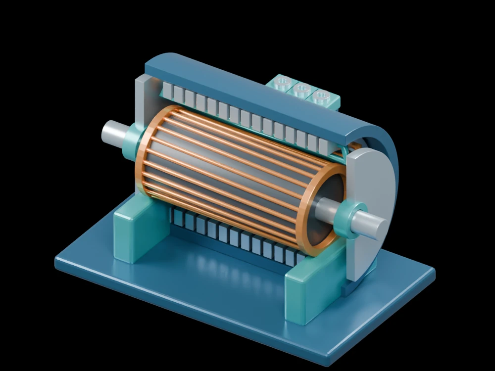
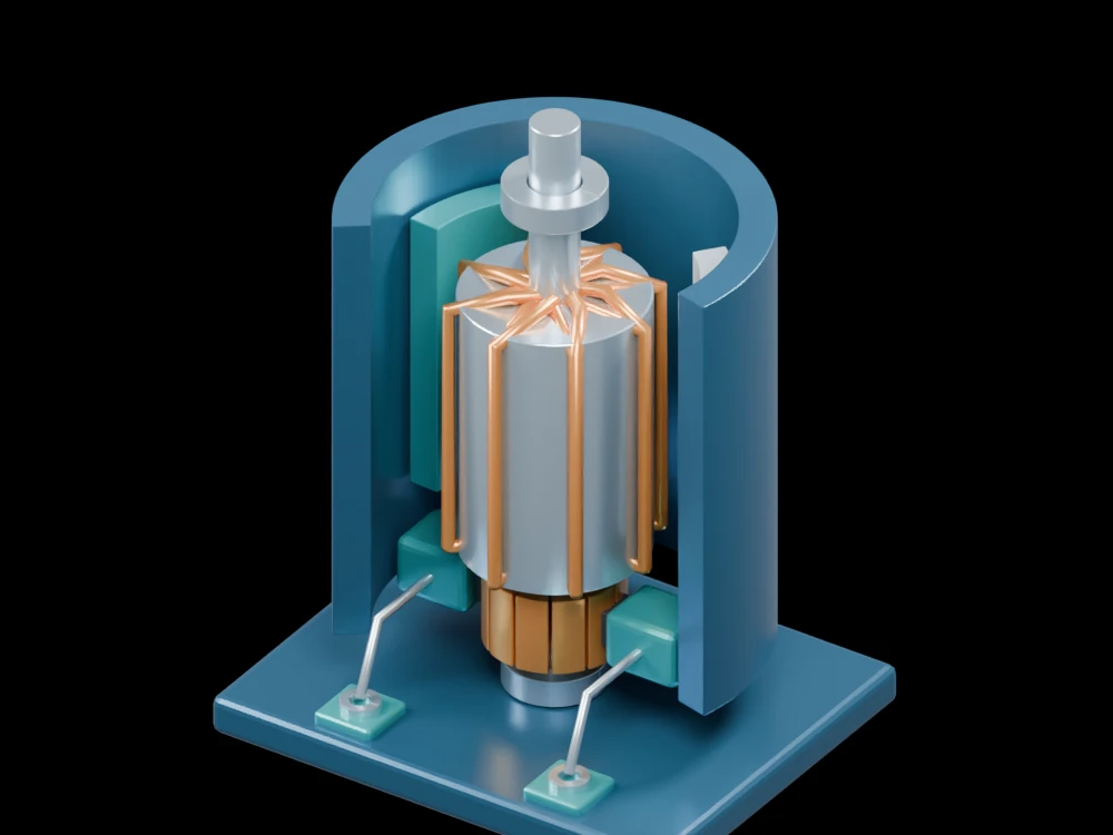
The brushed-motor model exposes the permanent magnets, wound armature, shaft, segmented commutator and brushes. Follow the electrical route into the rotating winding, then look at the air gap between rotor and magnets. That gap is where geometry influences magnetic forces. The model is a conceptual cutaway and does not reproduce the optimised pole shapes from the study.
Related articles
 Matched motor tests connect higher efficiency with lower heat
 An engineered environment changes a microscopic engine’s power–efficiency trade-offMagnetic measurements expose early fatigue changes in tested metalsChanging the character of noise shifts a microscopic engine’s best operating speedSwitching between unstable modes can stabilise a mechanical oscillatorA configurable joint reveals how small gaps turn motion into impacts
 An accordion-inspired pump recreates complex flow waveforms
 Dense liquid-metal coils combine soft actuation, sensing and communication
 A DNA clutch lets a magnetic nanomotor engage and disengage its rotorElastic electromagnetic mechanisms give small robots muscle-like motionElectric current drives a molecular rotor and changes its conductanceA stretchable fibre becomes a pump that can be woven into clothing
 Nanotextured surfaces help graphite maintain an extremely low-friction contactProjected light assembles and drives reconfigurable microscopic machinesLiquid-metal networks turn a flat elastomer into programmable 3D surfacesMicroscopy reveals which internal features hold a permanent magnet’s directionLight drives microscopic gear trains through patterned metasurfacesA soft pump runs on energy collected by a triboelectric generatorSoft robots steer their shape by combining local electromagnetic vectorsFriction consolidates brittle magnetic powders in a single processing stepA soft robot arm stays bendable while transmitting continuous torqueA soft pump moves liquid without a rotating impeller
 A quantum material rectifies signals from radio to terahertz bands
 A two-phase buck converter tackles the light-load efficiency problem
 A 100 kW solid-state transformer reaches 98.57% efficiency in testingA redesigned magnetic path cuts opening time in a solenoid study